Image Processing Reference
In-Depth Information
e
C
P
e
W
e
W
O
C
e
C
O
W
e
C
e
W
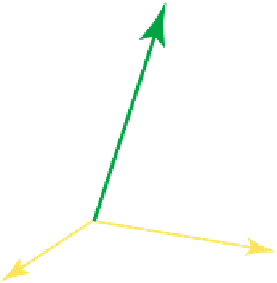
Fig. 13.3.
The camera and the world coordinate systems are shown in
yellow
and
green
,
respectively
13.2 World Coordinates
In this section we place the camera frame,
C
, into another frame, that we call the
world frame,
(Fig. 13.3). We will study how points represented in the camera
frame can be transferred to the world frame. This is useful because the camera frame
and the world frame are often in motion w.r.t. each other while the camera observes
the world. The camera and the world frames do not, in general, have axis parallel
basis vectors, which means that there is a rotation matrix (a tensor)
R
having the
elements
3
W
⎛
⎞
R
11
R
12
R
13
R
21
R
22
R
23
R
31
R
32
R
33
⎝
⎠
R
=
(13.20)
that can align them. Equivalently, the elements of
R
can be used to express the
camera basis by a linear combination of the world basis:
⎧
⎨
e
X
=
R
11
e
X
+
R
12
e
Y
+
R
13
e
Z
e
Y
=
R
21
e
X
+
R
22
e
Y
+
R
23
e
Z
e
Z
=
R
31
e
X
+
R
32
e
Y
+
R
33
e
Z
⇔
e
X
,
e
Y
,
e
Z
=
e
X
,
e
Y
,
e
Z
·
R
T
⎩
(13.21)
Here
e
X
represents a world basis vector and
e
X
represents a camera basis vector,
respectively. The interpretation of the other symbols is analogous. Note that entities
like
e
X
are abstract vectors that do not require a particular frame to exist. Defining
the camera and the world basis sets as
=
e
X
,
e
Y
,
e
Z
,
=
e
X
,
e
Y
,
e
Z
C
W
(13.22)
3
A rotation matrix
R
is an orthogonal matrix, i.e.
R
T
R
=
I
and
R
−
1
=
R
T
.