Image Processing Reference
In-Depth Information
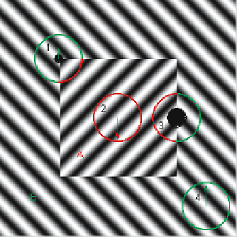
Fig. 10.11. Illustration of addition using the complex structure tensor. The linear symmetry
tensor components
I
20
are shown as vectors for four local images. The balanced direction
components,
I
11
, are shown as
circles filled with black
. The limits of images are marked by
color circles
I
20
=
k
2
=exp(
I
20
=
k
2
=exp(
i
π
i
π
2
−
)
)
2
I
11
=1
I
11
=1
In these images, the linear symmetry components point at directions given by
k
2
,
where,
k
is the direction of the respective gradient (Fig. 10.12, left). The balanced
direction components are equal to zero, because both images are linearly symmetric
so that
I
11
=
. In image 3 we have the structure tensor
Z
=
2
Z
+
2
Z
,having
|
I
20
|
the components
I
20
=
2
i
π
2
)+
2
exp(
i
π
2
exp(
−
)=0
I
11
=
2
+
2
=1
The linear symmetry component is zero, as it should be. The image is a perfectly
balanced image because none of its constituent directions dominates the others. The
balanced direction tensor element is, by contrast,
I
11
−|I
20
|
=1, which indicates
that all spectral power is distributed in such a way that the directions balance each
other perfectly. Conceptually, balanced image phenomenon is present also when the
gradient directions are random (Fig. 10.12, right). Likewise in image 1 we have the
structure tensor
Z
=
4
Z
+
4
Z
having the components
I
20
=
4
exp(
i
π
2
)+
4
exp(
i
π
)=
2
exp(
i
π
−
)
2
2
I
11
=
4
+
4
=1
Inparticular,thebalanceddirectioncomponent,
I
11
−|I
20
|
=
2
,shouldbecontrasted
=
2
to the magnitude of the linear symmetry component
|
I
20
|
. The argument of
I
20