Java Reference
In-Depth Information
Rule 3 is called the
nesting rule
. Repeatedly applying rule 3 to the simplest activity dia-
gram results in one with neatly
nested
control statements. For example, in Fig. 5.25, the
action state
in
the
simplest activity diagram
is
replaced
with
a
double-selection
(
if
…
else
)
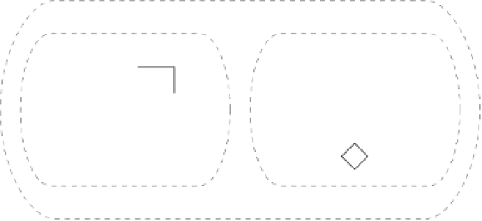
statement. Then rule 3 is applied again to the action states in the double-selection statement,
replacing each with a double-selection statement. The dashed action-state symbol around
each double-selection statement represents the action state that was replaced. [
Note:
The
dashed arrows and dashed action-state symbols shown in Fig. 5.25 are not part of the UML.
They're used here to illustrate that
any
action state can be replaced with a control statement.]
apply
rule 3
[f]
[t]
action state
apply
rule 3
apply
rule 3
action state
action state
[f]
[t]
[f]
[t]
[f]
[t]
action state
action state
action state
action state
Fig. 5.25
|
Repeatedly applying rule 3 of Fig. 5.22 to the simplest activity diagram.
Rule 4 generates larger, more involved and more deeply nested statements. The dia-
grams that emerge from applying the rules in Fig. 5.22 constitute the set of all possible
structured activity diagrams and hence the set of all possible structured programs. The
beauty of the structured approach is that we use
only seven
simple single-entry/single-exit
control statements and assemble them in
only two
simple ways.