Biomedical Engineering Reference
In-Depth Information
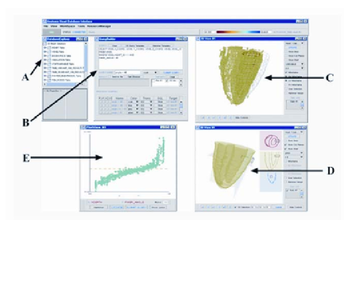
Figure 8
. "Screenshot" of the windows by which the user interacts with HeartScan. (
A
) win-
dow for viewing data tables; (
B
) SQL query window; (
C
) window for interactive 3D display of
heart data; (
D
) pull-down window for user selection of heart regions to query; (
E
) statistics
display window.
/#
M
b
(
x
)/G
b
(
x
,
t
) = 0, ~
x
in
B
,
[18]
where
x
is spatial position, G
i
(
x
,
t
) and G
e
(
x
,
t
) are the transmembrane intra- and
extracellular potentials, respectively;
v
(
x
,
t
) = G
i
(
x
,
t
) - G
e
(
x
,
t
) is the transmem-
brane voltage;
C
m
is the membrane capacitance per unit area;
I
ion
(
x
,
t
) is the sum
of the ionic currents per unit area through the membrane (positive outward);
I
app
(
x
,
t
) is an applied cathodal extracellular current per unit area; C is the ratio of
membrane area to tissue volume;
M
e
(
x
) and
M
i
(
x
) are the extracellular and intra-
cellular conductivity tensors, with
M
(
x
) =
M
e
(
x
) +
M
i
(
x
); G
b
(
x
,
t
) is the bath poten-
tial; and
M
b
(
x
) is the bath conductivity tensor. These parameters may be set, in
models of the normal heart, using values described by Pollard et al. (68) and
Henriquez et al. (70). Additionally, boundary conditions on the interface be-
tween the heart and the surrounding tissue, E
H
, and the body surface, E
B
, must
be specified. The first boundary condition specifies continuity of potential:
G
e
= G
b
on E
H
.
[19]
The second specifies continuity of current at the interface: