Environmental Engineering Reference
In-Depth Information
R
E
R
E
R
F
R
P
Q
P
R
P
Q
P
Q
PW
Q
F
R
B
Q
B
R
B
Q
B
(
a
)
(
b
)
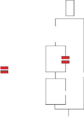
Figure 2.13
Equivalent circuit used to model the electrochemical behavior of (a) sealed
anodic i lm with hot water and (b) sealed with organic additives (hydrophobic i lm).
Abbrevations - indices capitals: B-barrier; P-porous layer; F-coating:conversion; E-electrolyte;
R-ohmic resistance; Q-constant phase element.
associated with the porous layer, R
B
: barrier layer resistance, Q
B
: CPE
parameters associated with the barrier layer, and CPW: capacitance associ-
ated with the pore wall; R
f
: electrolyte resistance in the pores of the organic
i lm/Q
f
: CPE parameters associated with the organic i lm.
h e clear dif erences observed between sealed and unsealed EIS spectra
can be transformed into reliable information about the sealing quality and
the stability of anodic i lms, according to previous studies which have pro-
posed dif erent equivalent circuits to simulate the properties of each layer
(barrier and porous layers) in the anodic i lm.
Aluminium respective aluminium oxide layers are both high impedance
systems. Application of an additional protecting layer increases the imped-
ance further. Due to the organic nature of the coatings, high values of the
resistance and the low values of the constant phase elements show good
protective properties against corrosion (Table 2.6). h e similar structures
make it possible to use the same equivalent circuit for all coated samples,
but the distribution of the values for the time constants is quite dif erent.
h erefore, although it seems that the Nyquist diagrams have miscellaneous
shapes, that is not the case (see Figure 2.14). In general, it can be said that
they are useful for comparing the corrosion resistance.


Search WWH ::

Custom Search