Environmental Engineering Reference
In-Depth Information
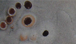
(a)
(b)
(c)
(d)
(e)
fiGure 1.4
Morphology of common gas bubbles associated with n-Fe
0
(nanofer Star (supplied by nanoiron s.r.o.; www.nanoiron.cz),
50 nm, BET = 20m
2
g
−1
; mixed with n-Al
0
and n-Cu
0
) (a) Oxygen bubbles encased by Cu
0
on the surface of n-Fe
0
[5 g n-Fe
0
+ 5 g n-Cu
0
+ 0.25 l
saline H
2
O [Eh = 0.095 V; pH = 7.01; EC = 1.993 mS cm
−1
; T = 12.8 C - gas composition checked using TCD GC]]. (b) O
2
gas venting where
n-Al
0
rests on top of n-Fe
0
. The O
2
gas bubbles are encased by n-Cu
0
. [5 g n-Fe
0
+ 5 g n-Cu
0
+ 5 g n-Al
0
+ 0.25 l saline H
2
O [Eh = 0.073 V;
pH = 7.00; EC = 1.981 mS cm
−1
; T = 12.9 C- gas composition checked using TCD GC]]. (c) O
2
gas venting where n-Al
0
rests on top of n-Fe
0
.
[5 g n-Fe
0
+ 5 g n-Cu
0
+ 5 g n-Al
0
+ 0.25 l saline H
2
O [Eh = 0.073 V; pH = 7.00; EC = 1.981 mS cm
−1
; T = 12.9 C- gas composition checked using
TCD GC]]. (d) O
2
filled spheres of n-Cu
0
developing on the n-Fe
0
- water interface, 5 min after loading into a reactor. [40% n-Fe
0
+ 20%
n-Cu
0
+ 40% n-Al
0
]. (e) H
2
gas bubbles developing on the ZVM-water interface (Fig. 1.4d), 3 weeks after loading [H
2
composition verified by
TCD GC]. Part of the n-Fe
0
has been corroded to form agglomerated FeOOH and Fe
3
O
4
nodules or clods (0.5-4 mm in diameter). Some of
the nodules are coated with n-Cu
0
. Each nodule forms an accreting galvanic cell (Fig. 1.2) with an anodic core (e.g., n-Fe
0
, n-Al
0
, Fe(OH)
2
)
and a cathodic exterior (e.g., n-Cu
0
, n-FeOOH, n-Fe
3
O
4
). Individual gas bubbles are 3-6 mm in diameter.
After the FeOOH corrosion products (Fig. 1.2) reach a critical mass, the ZVM switches from operating in a net recharge mode,
to operation in a net discharge mode. During this phase, distinctive hydrogen gas bubbles form on the ZVM/FeOOH surface
(Fig. 1.4e). Unlike the O
2
bubbles, H
2
bubbles are not associated with a specific cathodic ZVM, but instead form on the surface
(and in) active charge transfer sites (e.g., FeOOH, Fe
3
O
4
(Fig. 1.4e)).
1.3.3.2.2.6 galvanic type b reactions: hydrogen evolution The amount of hydrogen generated is a function of ZVM
composition, water composition, and operating conditions (pressure, temperature) [155-157]. The maximum hydrogen produc-
tion occurs when the n-ZVM is reduced to the ZVM oxide (Fig. 1.2). For example,
x
ZVM +
y
H
2
O = ZVM
x
O
y
+
y
H
2
. For the
reaction 3Fe + 4H
2
O = Fe
3
O
4
+ 4H
2
(Figs. 1.2 and 1.4e), 167 g n-Fe
0
(50 nm) + 72 g H
2
O = Fe
3
O
4
+ 8 g H
2
(89.64 l) [158]. This pro-
cess can be undertaken over a short time period using n-Fe
0
(50 nm). Increasing the temperature of a water:n-Fe
0
mixture from
<20 to 350°C over a 90-min period, in a sealed diffusion reactor, will result in a H
2
yield of about 450-540 m
3
H
2
t
−1
n-Fe
0
, and
a gas pressure of greater than 5 MPa [159]. Cooling the reactor to 20°C provides a deliverable H
2
gas at less than 3 MPa [159].
Reduction of the Fe
3
O
4
to Fe
0
allows the cycle to be repeated (e.g., Fe
3
O
4
+ 4CO = 3Fe
0
+ 4CO
2
; Fe
3
O
4
+ 4H
2
= 3Fe
0
+ 4H
2
O) [159,
160]. In a confined diffusion reactor, the general reactions (Fig. 1.2), result (at
T
= <50°C) in low levels of pressurized H
2
gas
evolution as the Fe
0
oscillates between charged (Fe
III
) and discharged (Fe
II
) states [155-157].
The oscillating combination of H
+
and e
−
generation from the cathodic sites during recharge and discharge [151, 153] creates
the driving force for chlorinated hydrocarbon (and other Type A) remediation [161].