Environmental Engineering Reference
In-Depth Information
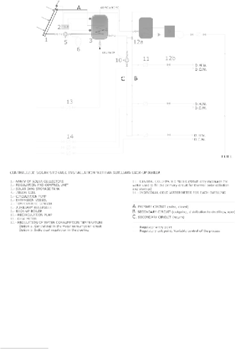
Figure 20.4.3
Diagram of a centralized solar storage system with an auxiliary back-up boiler for a
multi-dwelling building (courtesy of Solaris S.L.).
The design of a supplementary back-up system depends on the projected use (or
uses) of the installation. It is imperative that this system should switch on only when
strictly necessary so as to maximally exploit the energy obtained from the array of solar
collectors. All system components are interconnected by a series of hydraulic circuits
made up of pipes, pumps and other elements such as valves, expansion tanks, deaera-
tors, etc. The primary circuit connects the solar collectors to the heat exchange system
and transfers the solar energy to a fluid (e.g. water with anti-freeze) that transports the
heat. The secondary circuit connects the heat exchanger to the storage tank. Finally,
the consumption circuit carries the water to each consumer (see Figure 20.4.3)
21
.
21
The heat exchanger in Figure 20.4.3 is a coil located inside the storage tank. This diagram
does not include the circuit that connects the heat exchanger to the storage tank.
Search WWH ::

Custom Search