Environmental Engineering Reference
In-Depth Information
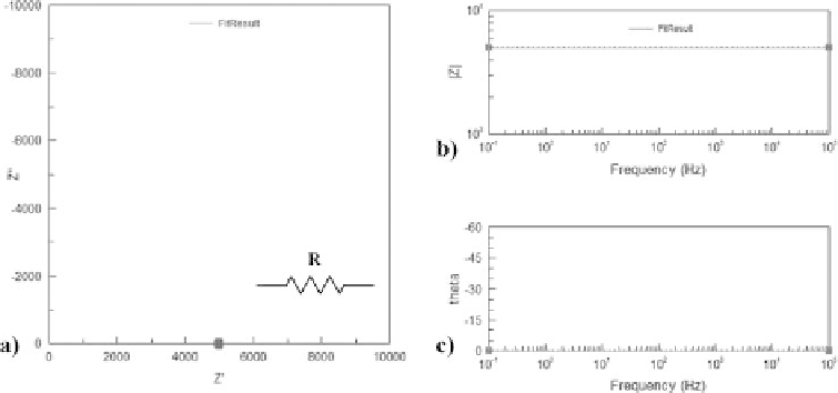
Figure 10.3.4
Graphical representation of the AC impedance of a resistor (
R
=
5k
): (a) Nyquist
diagram; (b) impedance Bode diagram; (c) phase Bode diagram.
10.3.2 Electrical analogues
EIS data usually represents the electrochemical systems as an electronic circuit, which
may consist of resistors, capacitors, inductors and more complex elements, assem-
bled in series or in parallel. Equivalent electrical analogues are a useful tool for the
interpretation of experimental results, by fitting the experimental data to specific
arrangements of electrical elements. This can provide relevant information concern-
ing reaction kinetics, ohmic conduction processes and even mass transfer phenomena
occurring in electrochemical systems. The different circuit elements in alternating cur-
rent (AC) are briefly described hereafter. However, complementary knowledge about
standard circuit elements is strongly encouraged (Barsoukov and Macdonald, 2005).
10.3.2.1 Ohmic resistance
The equivalent analogue for an ohmic conduction process is a simple resistor, which
according to the Ohm's law represents the resistance to electric charge transfer. For a
sinusoidal perturbation the impedance of a resistor
Z
R
in the complex plane is simply
defined as:
Z
R
=
R
(10.3.5)
For the case of a simple resistor, the correspondent Nyquist plot is just a point in the
real axis with value
R
with no imaginary component and independent of frequency -
Figure 10.3.4.
10.3.2.2 Double layer capacitance
An electrical double layer exists at the interface between an electrode and its surround-
ing electrolyte as shown in Figure 10.3.5. This double layer is formed due to the charge
Search WWH ::

Custom Search