Environmental Engineering Reference
In-Depth Information
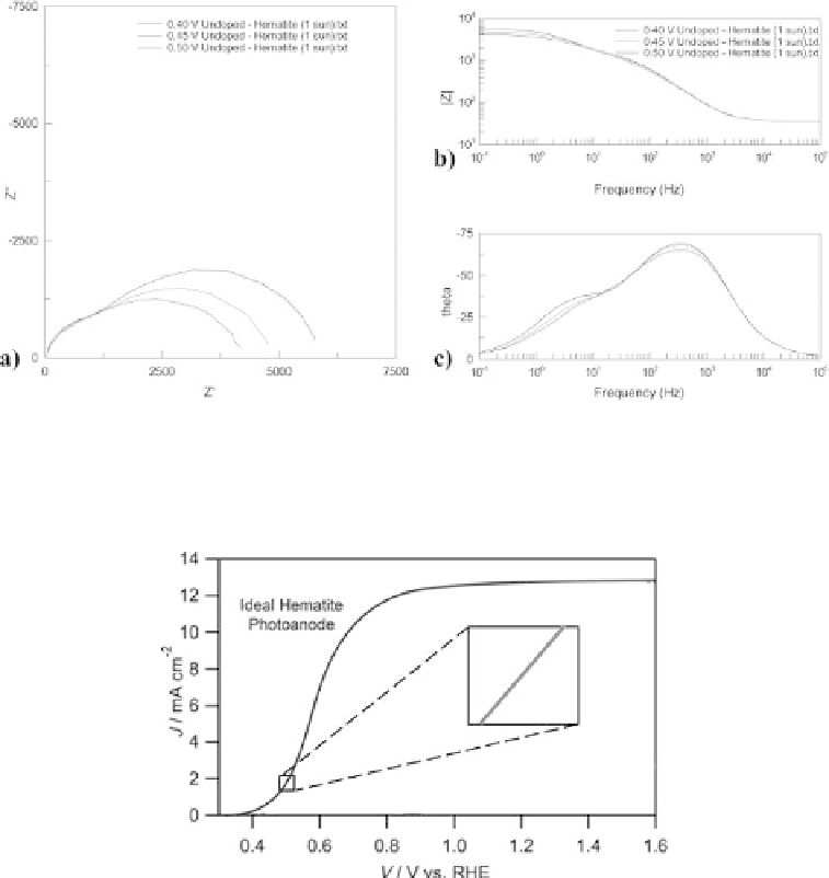
Figure 10.3.2
Graphical representation of theAC impedance of a PEC cell in 3-electrodesconfiguration:
(a) Nyquistdiagram; (b) impedance Bode diagram; (c) phase Bode diagram.
Figure 10.3.3
Current versus voltage curve showing pseudo-linearity. (Current-voltage characteristic is
a steady-state technique that determines the performance response of a photoelectrode
in the dark and under different light conditions. The I-V characteristic applied for water
splitting is usually performed in a three electrodes configuration (being the third one is
the reference electrode, usually Ag/AgCl)).
Attempting for the system under study, i.e. a photoelectrochemical cell for water-
splitting and its
I
V
characteristic shown in Figure 10.3.3, it is clear that the response
to a voltage input signal is not linear. The way to circumvent this situation is to consider
only a small portion of the cell's current
versus
voltage curve, which appears to be
linear - Figure 10.3.3. In practice, for EIS measurements a small voltage perturbation
(1-20 mV) is applied to the cell, ensuring that the response is in the pseudo-linear range
(Conway et al., 2002).
−
Search WWH ::

Custom Search