Environmental Engineering Reference
In-Depth Information
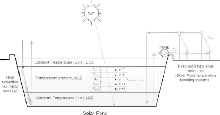
Figure 7.2.2
Schematic illustrating the vertical divisions of solar pond and external heat extraction and
addition.
to be at the middle of each division. By applying an energy balance to the divisions in
the different layers of the solar pond when extracting heat as shown in Figure 7.2.2, a
finite difference model can be developed for the temperatures of three adjacent nodes
(Wang and Akbarzadeh, 1982).
To estimate the performance of the initial temperature of the solar pond, density,
conductivity, specific heat capacity, thickness, depth, incoming solar radiation and
the time increment for each node are required as input boundary conditions. The
solar radiation that penetrates the solar pond surface is calculated using the formula
discussed by Bryant and Colbeck (Bryant and Colbeck, 1977)
h
=
H
[0
.
36
−
0
.
08 ln(
x
)]
.
(7.2.1)
Here
H
is the solar radiation reaching the top surface of the solar pond after deducting
the reflective losses;
h
is the solar radiation that penetrates the solar pond surface and
reached the depth of
x
.
7.3 SOLAR POND - CONSTRUCTION AND OPERATION
7.3.1 Set-up and maintenance
Initial steps in setting up a solar pond are very similar to that of constructing an artificial
fresh water pond, similar to the rain water collection pond used for irrigation. The
land is excavated and the excavated soil is used to build the side walls of the pond with
a slope of about 1:2 (Hull et al., 1989). The newly exposed pond floor is compacted
with heavy rollers and small sharp stones and dried soil clusters are removed before
laying the liners. The liners are then covered by a thin layer of locally available clay.
Search WWH ::

Custom Search