Environmental Engineering Reference
In-Depth Information
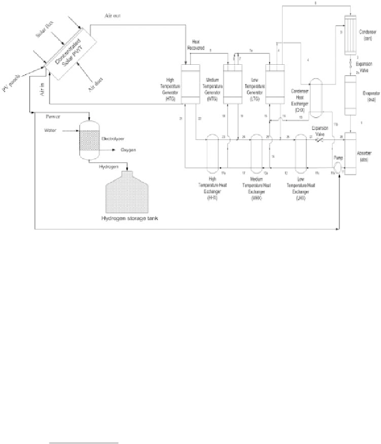
Figure 3.3.11
Schematic of integrated system.
system and is used as an energy source for the absorption cooling system. A detailed
description of this system can be found in Ratlamwala et al. (2011).
3.3.3.2 Energy and exergy analyses
Detailed energy and exergy analyses of solar PV/T system are presented in case study 2
or can be found in Ratlamwala et al. (2011).
The electrolyzer is used to split water molecules into hydrogen and oxygen
molecules, where hydrogen molecules are stored in the tank for later usage as an
energy provider to the HTG or as a fuel to produce power using PEMFC. The amount
of hydrogen produced depends on the efficiency of the electrolyzer, the heating value
of the hydrogen, and power input to the electrolyzer.
HHV
W
solar
−
W
pump
m
H
2
×
˙
η
elec
=
(3.3.21)
After getting the heat and power output from the PEM fuel cell, equations for
HTG were written in order to run the TEACS to achieve the cooling load. The amount
of energy provided to the HTG is shown below
Q
HTG
=
Q
so
(3.3.22)
The mass balance equations for HTG are given as follows
m
21
x
21
=˙
˙
m
22
x
22
+˙
m
8
x
8
(3.3.23)
Search WWH ::

Custom Search