Environmental Engineering Reference
In-Depth Information
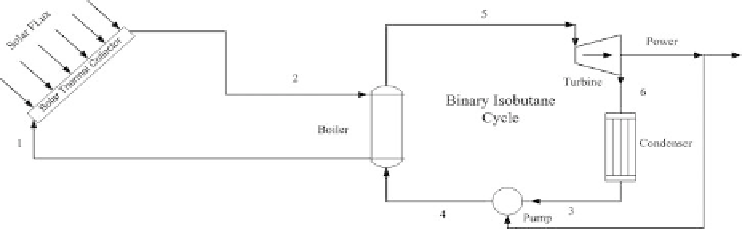
Figure 3.3.1
Schematic of solar thermal integrated with binary cycle.
the condenser. In the condenser, isobutane at state 6 loses heat to the environment to
leave at state 3 as saturated liquid in order to enter the pump where its pressure is
increased to that of state 4. The part of the power produced by the turbine is supplied
to the pump and remaining power is available for later use.
3.3.1.2 Energy and exergy analyses
The rate of heat gained by the air passing through the collector is calculated as
I
A
1000
×
Q
so
=
(3.3.1)
where
Q
so
represents rate of heat gained by the air passing through the collector,
I
represents solar flux, and
A
represents solar collector area.
The exergy destruction rate in the solar thermal collector is calculated as
Ex
1
+
Ex
so
Ex
2
+
Ex
de,so
=
(3.3.2)
where
m
1
(
h
1
s
0
)
Ex
1
=˙
−
h
0
)
−
T
0
(
s
1
−
1
I
T
0
T
sun
A
1000
×
Ex
so
=
−
m
2
(
h
2
s
0
)
Ex
2
=˙
−
h
0
)
−
T
0
(
s
2
−
Ex
1
represents exergy rate at state 1,
Ex
so
represents exergy rate of solar
where
Ex
2
represents exergy rate at state 2, and
Ex
de,so
represents exergy destruction
flux,
rate in the solar collector.
The power consumed by the pump is defined as
m
3
v
3
(P
4
−
P
3
)
W
p
=˙
(3.3.3)
η
p


Search WWH ::

Custom Search