Environmental Engineering Reference
In-Depth Information
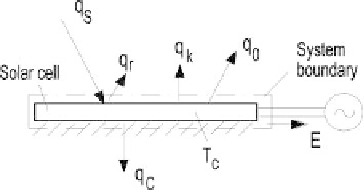
Figure 2.4.21
Energy streams of solar cell (from Petela, 2010).
q
k
and
q
0
, respectively, both transferred to the environment. Therefore, the energy
conservation equation for the considered system, defined by the system boundary is:
q
S
=
q
r
+
q
k
+
q
0
+
q
C
+
E
(2.4.107)
where
10
−
5
σT
S
q
S
=
2
.
16
×
(i)
q
r
=
ρ
C
q
S
(ii)
q
k
=
k
(
T
C
−
T
0
)
(iii)
ε
C
σ
(
T
C
−
T
0
)
q
0
=
(iv)
10
−
5
is the view (Sun-Earth) factor,
σ
is the Boltzmann radiation
constant of a black surface,
k
is the convective heat transfer coefficient and
T
0
is the
environment temperature. The solar cell surface is assumed to be perfectly gray at
emissivity
ε
C
, (reflectivity
ρ
C
and where 2
.
16
×
ε
C
).
The useful heat
q
C
can be determined from equation (2.4.107) if the electrical
energy
E
is known, e.g., from the measurement.
The solar cell can be evaluated by the energy electrical efficiency:
η
E
,
el
=
=
1
−
E/q
s
,by
the energy heating efficiency:
η
E
,
q
=
q
c
/q
s
, or by the energy cogeneration efficiency:
η
E
,
cog
q
c
)
/q
s
According to exergetic interpretation the exergy
b
S
incoming to the considered
surface from the Sun is split into the exergy
b
r
of reflected solar radiation, the exergy of
heat
b
0
radiating to the environment, exergy of heat
b
k
transferred to the environment
by convection, exergy of useful heat
b
C
transferred from the solar cell to its interior,
electric energy
E
and the exergy loss
δb
due to the irreversibility of the considered
system. Thus, the exergy equation for the system shown in Figure 2.4.21 is:
=
(
E
+
b
S
=
b
r
+
b
k
+
b
0
+
b
C
+
E
+
δb
(2.4.112)
where:
10
−
5
σ
3
(3
T
S
+
T
0
−
4
T
0
T
S
)
b
S
=
2
.
16
×
(v)
Search WWH ::

Custom Search