Environmental Engineering Reference
In-Depth Information
The net of removal in a CSTR is given by
e
−φ
H
s
)
C
w
C
0
=
S(
1
−
R
CSTR
=
1
−
e
−φ
H
s
)
,
(6.104)
1
+
S(
1
−
and for a PFR
C
w
C
0
=
e
−φ
H
s
))
.
R
PFR
=
1
−
1
−
exp
(
−
S(
1
−
(6.105)
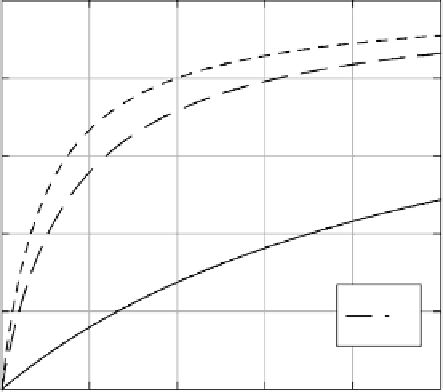
A general nomograph can be drawn to obtain the removal efficiency as a function
of both
S
and
H
s
. Figure 6.20 represents the nomograph. With increasing
S
,
R
increases. For a given
S
, increased
φ
H
s
can be large if
K
w
a
is large. Large values of
S
can be realized if either
Q
g
/Q
L
or
K
aw
is large. Since
a
(V
w
/V
a
)
φ
H
s
increases the value of
R
.
φ
6
/D
b
(where
D
b
is the average bubble diameter or more accurately the
Sauter mean bubble diameter), decreasing the bubble size could markedly improve
the aeration efficiency. The nomograph is useful in designing the size (volume) of a
reactor required to obtain desired removal efficiency if the values of liquid and gas
flow rates are fixed for a given compound.
In some wastewater aeration ponds one encounters a thin layer of oil or a sur-
factant foam above the water layer as a natural consequence of the composition of
wastewaters. The oil layer can act as an additional compartment for the accumulation
of a pollutant from the aqueous phase. The solute activity gradient between the aque-
ous and oil layers helps establish transport from solvent to the aqueous phase which
competes with the unidirectional solute transport by air bubbles from the aqueous
=
1
0.8
0.6
0.4
Φ
H
s
0.1
1
10
0.2
0
0
2
4
6
8
10
S
FIGURE 6.20
Nomographforsteady-stateremovalinanaerationlagoonoperatedasaCSTR.
Air bubbles are introduced at a depth
h
s
below the surface of water.


Search WWH ::

Custom Search