Graphics Reference
In-Depth Information
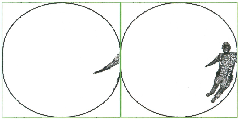
Figure 13.9. The same sample scene as shown in Figure 13.8, except with the geometry rasterized in wire-
frame. Model courtesy of Radioactive Software, LLC,
www.radioactive-software.com
.
Created by Tomas
Drinovsky, Danny Green.
seen in the figures. In addition, Figure 13.9 shows the same scene rendered in wireframe
rasterization mode.
13.2.3 Sampling Paraboloid Maps
Now that we have generated the paraboloid maps, we must properly sample them when
rendering a reflective object into the final output render target. This process uses only the
vertex and pixel shader stages, and it follows a more traditional rendering technique. The
only required input vertex data are the object space position and normal vectors. The vertex
shader begins by transforming the vertex position to world space. This world-space posi-
tion is then used to calculate the world-space vector from the camera to the vertex. In ad-
dition, the vertex shader calculates the world-space normal vector, and of course produces
the clip space position for passing on to the rasterizer stage.
cbuffer ParaboloidLookupParams
{
matrix WorldViewProjMatrix;
matrix WorldMatrix;
matrix ParaboloidBasis;
float4 ViewPosition;
}
Texture2DArray ParaboloidTexture
: register( t0
);
SamplerState ParaboloidSampler
: register( s0 );
Search WWH ::

Custom Search