Graphics Reference
In-Depth Information
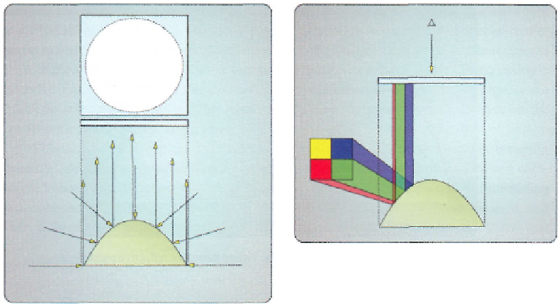
Figure
13.4.
A profile view of the virtual viewer,
the paraboloid, and an object being rendered into
the paraboloid map.
Figure 13.3.
The projection of a paraboloid onto a
plane.
The concept shown in Figure 13.3 is the key to the entire paraboloid environment
mapping technique. This ability to project the paraboloid contents onto a plane can be
mapped to a render target, where the region of the render target represents the domain
we have already described
—
where
x
and
y
are constrained to the [-1,1] region. We can
dynamically generate the contents of this render target by performing a paraboloid projec-
tion on the scene contents, and can effectively produce a form of an environment map for
half of the scene. If we use two "paraboloid maps" that are oriented 180 degrees from one
another, we can capture the entire contents (both halves) of a scene surrounding the origin
of the coordinate space. The challenge is to define precisely how we will perform the pa-
raboloid projection when generating the paraboloid maps, and inversely, how to properly
look up a particular point in the paraboloid maps when they are used to query the scene
while rendering a reflective object.
13.1.1 Paraboloid Map Generation
When generating a paraboloid map, the desired effect is to place each vertex of a model
into the location of the render target that corresponds to where that vertex would be seen
in the reflective paraboloid. Thus we need to know where we would consider the viewer
to be looking at the paraboloid, where the paraboloid is positioned, and where the vertices
are that are being transformed. If we assume that the scene surroundings are sufficiently far
Search WWH ::

Custom Search