Graphics Reference
In-Depth Information
Phase four, shown in Figure 9.20, is where the next big chunk of work takes place,
but before this, the group must have a plane from which to measure offsets, as shown in
Figure 9.19. This only requires a single thread and simply implements the plane-from-
point-and-normal equations, as shown in Listing 9.14.
// The
following
fragment
of the
compute shader
uses
//
this
utility function:
float4
CreatePlaneFromPointAndNormal(float3
n, float3
p)
{
return float4(n, (-n.x*p.x
-
n.y*p.y -
n.z*p.z));
}
//
Phase 3 of the CS starts
here:
if(GI
== 0)
{
// Let
the
first thread
only determine
the plane coefficients
// First,
decide
on the
average
normal
vector
float3 n
=
normalize
(
rawNormals[0][8]
+ rawNormals[0][1]
+
rawNormals[l]
[0]
+
rawNormals[l]
[1]
);
//
Second,
decide
the
lowest point on
which
to base it
float3 p
= float3(0.0f,le9f,0.0f);
for(int
i = 8;
i
< 2; ++i)
for(int j
= 0;
j
<
2;
++j)
if
(
corners
[i][j].y < p.y)
p
=
corners[i]
[j]
;
II
Third, derive
the plane
from point+normal
plane
= CreatePlaneFromPointAndNormal(n,p);
}
GroupMemoryBarrierWithGroupSync();
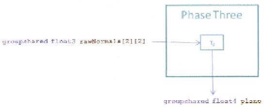
Listing 9.14.
Phase three of the compute shader.
Figure 9.19. Compute shader phase three.
Search WWH ::

Custom Search