Graphics Reference
In-Depth Information
More intelligent implementations could implement the idea of a near plane as well as
a far plane, consider a nonlinear scale (similar to depth buffers) to apply more detail nearer
the viewer, and consider using entirely different metrics. One more expensive possibility
mentioned earlier is to use screen-space contribution as the LOD scalar; simply project the
bounding coordinates to projection space and compute the area. A patch that contributes
more pixels to the screen should have a higher LOD.
The final section of Listing 9.8 assigns the raw values to the outputs expected by
Direct3D, which hides a couple of subtle details. First, as commented in the code, the
choice of interpolating up or down the LOD scale—either is acceptable, but the choice
will influence how much new geometry is generated—thus becomes a decision on quality
versus performance. Second, and much less obvious, is the effect of the ordering of tessel-
lation factors in the output array.
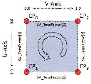
The Direct3D 11 specification defines, for a quad, that the 0
t
h
element is
U=
0.0, the
1
s
t
is
V=
0.0, the 2
n
d
is
U=
1.0, and the 3
r
d
is
V=
1.0. These
U
and
V
coordinates come
into play downstream in the domain shader, but their life begins here. Incorrect ordering
is a very easy bug to introduce and can generate unexpected results. Figure 9.7 shows this
pattern in the context of this implementation.
In this case, the pattern is transposed from the more conventional texture coordinate
system, but only for convenience and consistency throughout the implementation—there
is no particular reason why it must be this way.
Note that the hull shader constant function has visibility of all upstream data provided
by the vertex shader, and that this code, unlike the control point shader function, only pro-
duces additional intermediary values and does not remove any existing data.
These six output tessellation factors, stored in the HS_PER_PATCH_OUTPUT struct, are
forwarded to the fixed-function tessellator stage, which is the next pipeline stage after the
hull shader.
Step 3: The Domain Shader
By the time execution reaches the domain shader,
we are only concerned with the patch being ren-
dered. This is confirmed by the fact that it only
has visibility of the four control points (CP
0
-CP
3
in Figure 9.7) making up the patch itself, and has
no knowledge of the four neighboring patches.
The fixed-function tessellator has now generated
a number of new vertices to match the primitives
required to render this tessellated patch.
It is now the job of the domain shader to
take individual
UV
coordinates and turn them into
Figure 9.7.
Output element ordering for a
single tile.
Search WWH ::

Custom Search