Graphics Reference
In-Depth Information
information as per-vertex attributes, the geometry shader has no knowledge of the tessel-
lation work that preceded it.
Unlike in Direct3D 10, where the number of geometry shader invocations was di-
rectly linked to the parameters of a draw call by the number of primitives passed into
the pipeline, the number of executions when tessellation is enabled is now linked to the
SV_TessFactor and SV_InsideTessFactor values emitted from the hull shader con-
stant function (see Figure 4.8). If these are constant and/or set by the application (such as
through a constant buffer), you can derive the number of geometry shader invocations, but
if a more intelligent LOD scheme is implemented, the number of invocations will be much
more difficult to predict.
4.2.7 Rasterization and the Pixel Shaders
Tessellation is a geometry based operation. This means that the final rasterization stages
remain completely unchanged and oblivious to anything that came before it.
4.2.8 Demonstration of Possible Outcomes
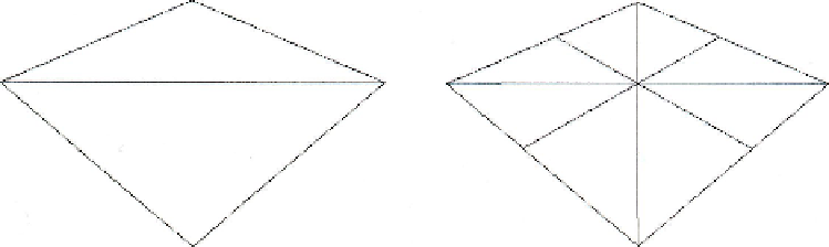
Earlier in this section, Figure 4.2 showed the "plain" 4-vertex quad of control points.
This is the original data sent by the application. The result of the above flow of execution
through the Direct3D 11 pipeline transforms Figure 4.9 into Figure 4.10.
In Figure 4.10, you can see the four triangles generated for each input triangle, and
you can see that for a 2.0 integer partitioning, it simply splits each edge in half. The next
section will detail the tessellation parameters.
Figure 4.11 demonstrates tessellation in a more complex setting. Taken from the
DetailTessellationll sample in the Microsoft DirectX SDK, it shows the result as it
would be seen in the final rendered image, as well as the wireframe representation, which
Figure 4.9.
Without tessellation enabled.
Figure 4.10.
With tessellation enabled.
Search WWH ::

Custom Search