Graphics Reference
In-Depth Information
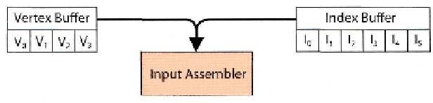
Figure 4.3.
Input assembler stage.
4.2.1 Input Assembler
With Direct3D 11 it is now possible to create primitives with up to 32 vertices. But regardless
of this, the input assembler functions exactly as it did in previous versions. It uses the ver-
tex declaration (an ID3DllInputLayout created from an array of D3D11_INPUT_ELEMENT_
DESCs), a vertex buffer (an ID3DllBuffer with binding of D3D11_BIND_VERTEX_BUFFER)
and an index buffer (another ID3DllBuf f er with a binding of D3D11_BIND_INDEX_BUF FER)
(see Figure 4.3). The topology set on the device will be D3Dll_PRIMITIVE_T0P0L0GY_n_
CONTROL_POINT_PATCHLIST, where n is between 1 and 32. The input assembler will then
read the index buffer in chunks of n and will pick out the appropriate vertices from the
vertex buffer.
4.2.2 Vertex Shader
Chapter 3 introduced the subtle difference between
control points
and actual vertices; with
tessellation, the vertex shader no longer has to output a clip-space vertex to SV_Position,
as in Direct3D 10 (see Figure 4.4). (Technically, this could be done in a geometry shader
in D3D10, but it was often more efficient to stick with the conventional vertex shader
approach.) It is now completely free to operate on data in whatever form the application
gives it (through the input assembler) and output that data in whatever coordinate system
or format it chooses.
The common use-case for a vertex
shader with D3D11 tessellation will be for
animation
—
transforming a model accord-
ing to the bones provided for a skeletal
animation is a good example (and will be
covered in more detail as part of Chapter 8).
In this example, the vertex shader simply
transforms the model-space vertex buffer
data into world-space for the later stages.
Note that once the vertex shader has
Figure 4.4. Vertex shader stage.

Search WWH ::

Custom Search