Graphics Reference
In-Depth Information
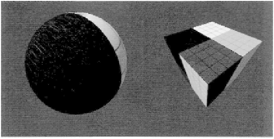
Figure 3.68. A sample of using the linear interpolation mode.
The linear mode.
When the linear interpolation mode is used, the attributes that are
generated for each fragment will be linearly interpolated, taking perspective effects into
account. The need for perspective-correct interpolation arises from the fact that the per-
spective projection is not a linear operation, and this interpolation is performed after the
projection. This means that standard linear interpolation can't be used between vertices in
screen space, but instead, the depth of each vertex must also be taken into account.
The perspective effect can be accounted for in the interpolation process by dividing
each vertex attribute by its depth from the viewer before interpolation. The depth value is
found for each vertex as its (
W
-value, after projection, but before the conversion to normal-
ized device coordinates. The reciprocal of
W
is also calculated, and then interpolated, along
with these modified attributes. After all of these values are interpolated for each rasterized
fragment, the interpolated reciprocal of
W
is used to extract the original desired attribute,
which will produce a perspective-corrected interpolation value. This is the most common
interpolation mode, with texture coordinates on a three-dimensional model providing a
perfect example of when they are needed. Perspective-correct interpolation is needed not
only for texture coordinates, but is also needed if a position or direction vector (or any other
linear attribute) from a linear space (such as world space or view space) comes into the post-
projection stages. An example of the linear interpolation mode is shown in Figure 3.68.
The noperspective mode.
When the noperspective interpolation mode is used, the in-
terpolated attributes are strictly interpolated according to their two-dimensional position
on the render target. In essence, you can consider the geometry as being projected onto the
render target before the interpolation is performed. This interpolation mode implements
standard linear interpolation between vertices based on their positions. The interpolation
of attributes without perspective correction can be performed whenever the vertices being
interpolated all are at the same depth, such as when constructing an onscreen user interface
rendering. Figure 3.69 demonstrates the use of this interpolation mode.
Search WWH ::

Custom Search