Graphics Reference
In-Depth Information
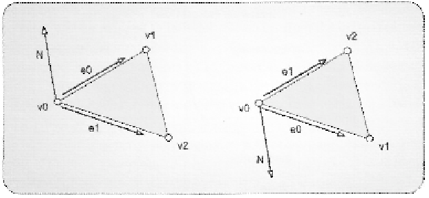
Figure 3.53. Two triangles with differing vertex windings.
We have seen that in the rasterizer state configuration, there are two different set-
tings for the culling operation: CullMode and FrontCounterClockwise. Specifying which
vertex winding represents a front-facing primitive depends on the input data introduced to
the pipeline in the input assembler stage. The digital content creation tool that was used to
generate the input geometry may use either winding, but it is common to have the option to
reverse the winding, to make the model compatible with the convention of the end user's
application. Reversing the vertex winding order is performed by swapping two of the ver-
tices from their current locations in the primitive's list of vertices.
Once the convention of what represents the front face of a primitive has been speci-
fied by the FrontCounterClockwise parameter, the CullMode parameter determines which
faces, if any, should be culled. Culling is used to reduce the amount of work required by the
rasterizer stage by eliminating triangles that are facing away from the current view point. If
a triangle faces away from the current view, it is considered to be back-facing. In traditional
opaque rendering algorithms, back faces do not contribute to the final image and should
be eliminated. In fact, roughly half of the primitives that enter this stage will be removed,
since only half of a model can be visible in a single view within a frame. In this case, the
CullMode parameter should be set to D3D11_CULL_BACK.
At the same time, there are many algorithms that require rendering geometry multiple
times with different cull modes to achieve different effects. For example, a simple tech-
nique for finding the thickness of an object at every pixel is to first render it with front faces
being culled and writing to the red channel of the render target, while using a blending state
that selects the maximum value when writing to the render target.
2
9
A second rendering
pass is performed with back faces being culled and writing to the green channel of the ren-
der target, while using a blending state that selects the minimum value when writing to the
render target. After these two passes, the render target contains the farthest point in the red
2
9
Blending will be covered in more detail in the output merger section of this chapter.
Search WWH ::

Custom Search