Graphics Reference
In-Depth Information
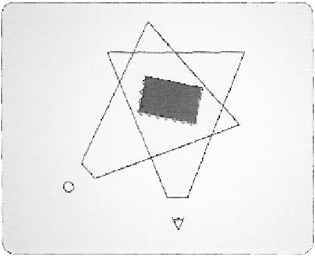
Figure 3.51, A mismatch between a scene rasterized from the light point of view and from the camera point
of view.
the distance from the light in each of its pixels. In the subsequent rendering pass, an object
is rendered from the viewer's perspective and the depth map is sampled from the first to
determine if it can be "seen" by the light and hence would receive light from it. In theory,
this is a very sensible way to determine which objects are in shadow and which are not.
But in reality, this method can introduce many artifacts, due to differences in the effective
sampling patterns of the two rendering passes.
2
8
This is demonstrated in Figure 3.51, which
displays an overhead view of an object and how it is rasterized by both the light's depth
map and by the scene rendering.
To combat this type of effect, the rasterizer stage provides a method to introduce
a depth bias into the generated fragments. The DepthBias and SlopeScaledDepthBias
settings provide a constant and a slope-based offset depth value, respectively. These two
parameters apply a depth bias in one of two ways, depending on the type of depth buffer
being used. Equation (3.4) and Equation (3.5) provide the two depth calculations.
Bias = (float)DepthBias * r + SlopeScaledDepthBias * MaxDepthSlope;
(3.4)
Bias = (float)DepthBias * 2 (exponent(max z in primitive) - r) +
SlopeScaledDepthBias * MaxDepthSlope;
(3.5)
2
8
Many, many, many algorithms have been devised to improve the produced image quality when using shadow
maps. A search in academic literature will easily return more than 100 different papers on the topic.
Search WWH ::

Custom Search