Graphics Reference
In-Depth Information
3.10 Rasterizer
203
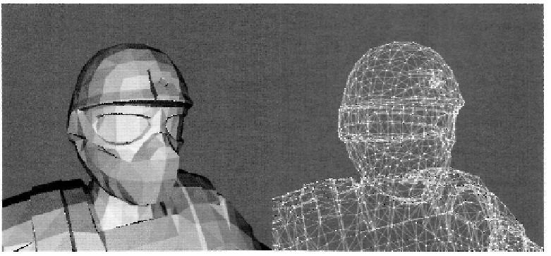
Figure 3.50. The difference between wireframe and solid fill modes. Model courtesy of Radioactive
Software, LLC,
www.radioactive-software.com
.
Created by Tomas Drinovsky, Danny Green.
We will examine each of the elements of the rasterizer state individually. The first
setting is the FillMode parameter, which determines how primitives are rasterized. The
available options are solid fill or wireframe. In solid fill, fragments are generated be-
tween the vertices of the primitive to completely fill its interior, while in wireframe mode
only the edges of a primitive are rasterized. In practice, this only affects triangle primitives
since lines only consist of a single edge, and points only consist of a single point, so the
fill modes are equivalent for them. Figure 3.50 shows a simple example of the difference
between these two modes for a triangle.
The second setting in this structure is the CullMode. The cull mode controls the cull
operation of the rasterizer stage. This can be used to enable culling of primitives that are
facing the viewer (
frontfacing)
or facing away from the viewer (
backfacing).
An option is
also provided to disable the culling operation entirely. Determining if a triangle is front fac-
ing or back facing is done by examining the order that its vertices arrive in. If the vertices
are ordered such that traversing them in order produces a clockwise trip around the triangle
on the render target, it has
clockwise
vertex ordering. Otherwise, the triangle is said to have
counter-clockwise
winding. The FrontCounterClockwise setting determines if the front-
facing triangles should be considered clockwise or counter-clockwise. In effect, this setting
is used with the CullMode to select the target of the culling operation.
The next three settings control an optional feature to provide a depth bias to the
fragments generated by the rasterizer. Some algorithms require an object to be rendered
in two different ways to two separate render targets to achieve a particular effect.
Shadow
mapping
is probably the most common example of this, where an object is rendered from
a light source's perspective to generate a map of what objects in the scene are visible to
the light. This rendering produces what is called a
depth map
for the light, as it determines
Search WWH ::

Custom Search