Graphics Reference
In-Depth Information
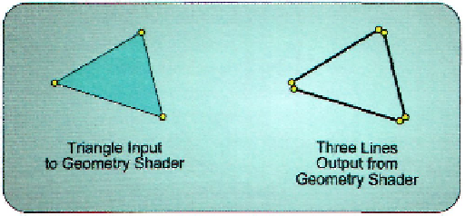
Figure 3.40. Splitting a triangle into three lines to provide a customized wireframe rendering.
of the shadow volume at that pixel, then that point in the scene lies on the far side of the
shadow volume and hence should be illuminated.
Before the geometry shader existed, shadow volume extrusion had to be performed
on the CPU and then passed to the GPU to be rasterized into the stencil buffer. However, the
geometry shader can easily detect when a triangle is located at the silhouette by comparing
its face normal vector to the adjacent triangle face normal vectors. If the current triangle is
facing the camera, and at least one adjacent triangle is facing away from the camera, then
the edge that the two triangles share should be extruded as a part of the shadow volume. If
a triangle is not a portion of the silhouette, the geometry shader can discard it by simply not
outputting its vertices. In this way, the geometry shader reduces the workload downstream
in the pipeline by eliminating unneeded geometry from further processing.
Point Sprites
Since the geometry shader receives primitives in its input array of vertices and it can de-
clare the type of output stream it wants, there are no restrictions regarding the input and
output primitive types. In combination with the geometry shader stage's ability to produce
a variable number of vertices, this allows for complete control over primitive type conver-
sion. For example, a triangle passed into the geometry shader can be converted to three
lines representing the edges of the triangle. This is a simple way to implement a wireframe
rendering scheme. The creation of the individual triangle edges is shown in Figure 3.40.
Another popular primitive conversion technique is to convert point primitives into
a pair of triangles that form a quad. These quads can then have a texture applied to them,
which effectively converts point geometry into a sprite. This process is typically referred
to as
creating point sprites,
and is frequently used to give particles in a particle system
a more compelling appearance. The process of creating point sprites is demonstrated in
Figure 3.41. An example of this technique is used in Chapter 12 to add textures to the par-
ticles in the particle system example.
Search WWH ::

Custom Search