Graphics Reference
In-Depth Information
is typically written in the SV_Position system value semantic, which must be present in
the input to the rasterization stage. In addition, any other per-vertex attributes required to
determine the final pixel color are also added to the domain shader output.
It is possible that the geometry shader stage can be either active or inactive, depend-
ing on the desired pipeline configuration. If it is active, output from the domain shader
is passed to the geometry shader stage, where it is consumed as complete primitives (re-
member that the primitive information in this case was generated at the tessellator stage).
Otherwise, the output is passed directly to the rasterizer stage, where it is also consumed
as primitives.
3.8 Geometry Shader
The geometry shader is the final pipeline stage that can manipulate the geometry being
passed through the pipeline before it is rasterized. It is a programmable stage and has
several unique capabilities not found in any other stage, including the ability to program-
matically insert/remove geometry in the pipeline, the ability to pass geometry information
to vertex buffers through the stream output stage, and the ability to produce a different
primitive type than is passed into it. This provides some very interesting use cases for this
stage, which are outside of the traditional pipeline model, ranging from saving processed
geometry data to a file, pipeline operation debugging, and of course, rendering operations.
The geometry shader stage also operates on complete primitives, including adjacent primi-
tive information, which provides the additional ability to analyze and test various aspects
of each primitive and perform customized calculations, depending on the geometry and its
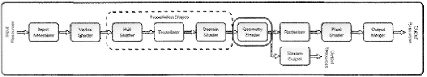
immediate neighbors. The location of the geometry shader stage in the pipeline is high-
lighted in Figure 3.35.
The geometry shader stage receives a list of vertices that represent the input primitives.
It is then free to pass these vertices to an output stream, where they are then re-interpreted
Figure 3.35. The geometry shader stage.
Search WWH ::

Custom Search