Graphics Reference
In-Depth Information
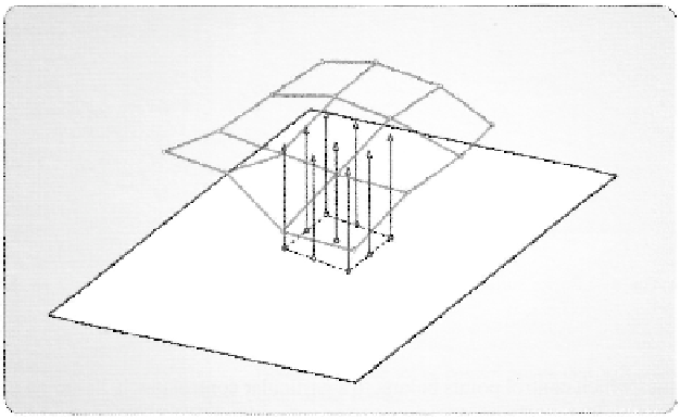
Figure 3.34. The generation of vertex locations in the domain shader for our 4x4 Bezier surface example.
Finally, the domain shader program must be able to receive the control patch, along
with one coordinate point for each invocation of the domain shader, and produce a vertex
that represents the Bezier surface. This is basically performed by evaluating the equations
for Bezier surfaces, where each of the control points contributes to the calculated location
of the vertex. The amount of the contribution is determined by the coordinates, which more
or less specify the proximity to each of the control points where we are evaluating. Once
this location has been calculated, the position is produced by the domain shader and is
passed down the pipeline for further processing. This is shown in Figure 3.34.
Of course, the domain shader will normally need to calculate more than just the posi-
tion of each of the tessellated vertices. One attribute that will be required most of the time
is a normal vector to be used for lighting calculations further in the pipeline. However, this
follows the same process we have discussed for position determination. The only differ-
ence is that we must calculate the normal vector in the domain shader program, in addition
to the position. This is also true for any other attribute needed for rendering. It must be
calculated from the available information, even if it is simply read from per-control point
attributes.
3.7.4 Domain Shader Pipeline Output
After the required attribute data is calculated, the newly created vertices are returned by the
domain shader program and passed to the next stage. The position output from this stage
Search WWH ::

Custom Search