Graphics Reference
In-Depth Information
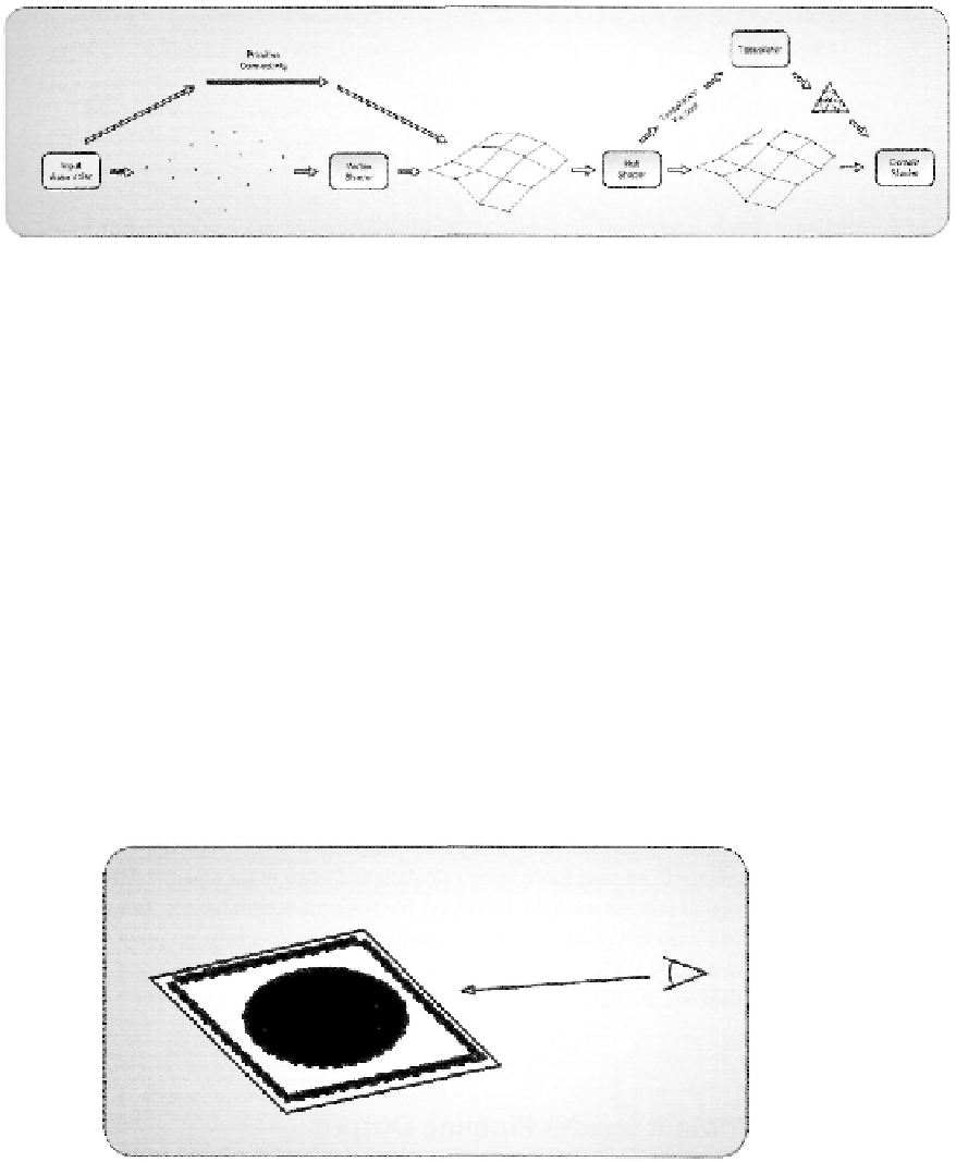
Figure 3.32. Our 4x4 Bezier surface as it is passed through the input assembler, vertex shader, and hull
shader stages.
it determines which control points belong to a particular control patch, based on the indices
provided in an index buffer and its primitive type setting (a 16-point control patch in this
case). The control patch points are read by the vertex shader and passed to the hull shader.
The 4x4 group of control points is then read by the hull shader and passed to the domain
shader in the same 4x4 control patch configuration. The process up to this point represents
step one in our block diagram from Figure 3.30. Figure 3.32 depicts this process.
Next, the patch constant function must calculate the needed tessellation amount to
sufficiently represent our Bezier surface in the given viewing conditions. This can take into
account the size of the control patch, the distance from the current view point, or any num-
ber of other metrics. The required tessellation factors are passed to the tessellation stage,
which converts that data into a series of coordinates within the domain. Those points are
then passed to the domain shader stage. This represents step two in our tessellation process,
and is depicted in Figure 3.33.
Figure 3.33. Determining the required edge factors for a particular quad, based on the current viewing
conditions.
Search WWH ::

Custom Search