Graphics Reference
In-Depth Information
i
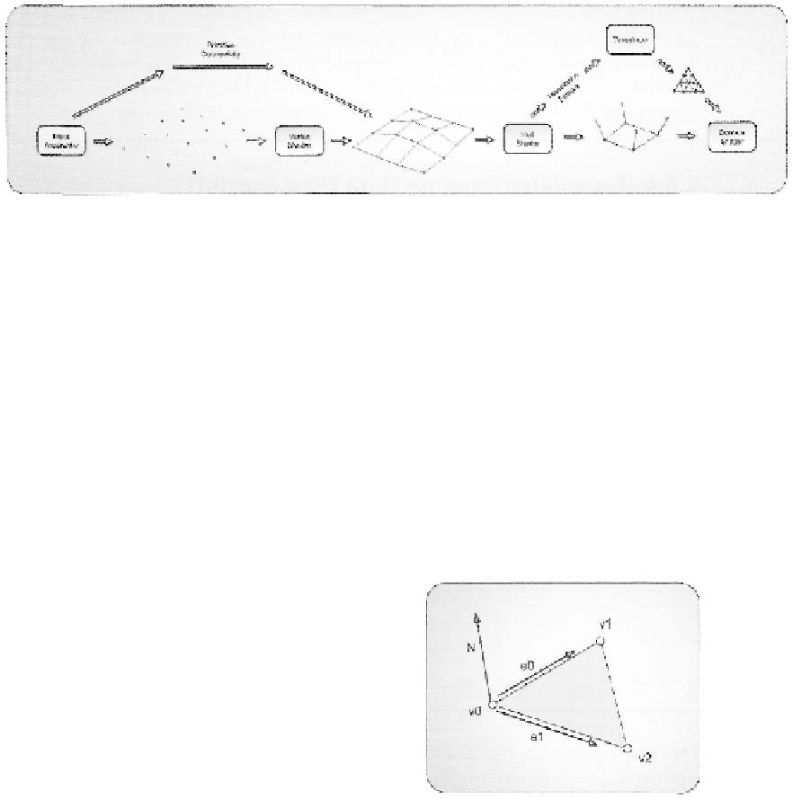
Figure 3.26. Primitive data flowing through the pipeline, up to through the tessellation stages.
of input data, simply because this stage only consumes a maximum of five floating point
values for tessellation factors.
Primitive Generation
The second step in the tessellator stage is to generate the required primitive information
needed to use the sampled locations as renderable geometry later in the pipeline. You may
wonder why the primitive data must be generated in this stage, since a primitive topology
was specified in the input assembler stage. In fact, it is correct that the input assembler cre-
ates primitive connectivity information that skips the vertex shader stage and is passed to
the hull shader stage when the tessellation system is active. However, when the tessellation
stages are active, the input primitive from the input assembler stage must be one of the
control patch types. This specifies the connectivity of the vertices as control points and de-
fines a control patch, instead of a primitive type that can be rasterized directly. Figure 3.26
visualizes the distinction in how primitive data flows through the pipeline up to the end of
the tessellation system.
We have already seen that the type of out-
put primitive is specified by the outputtopology
attribute. When lines are being generated, they
have no front or back side, so it isn't important in
what order the vertices are arranged in within the
primitive. However, when triangles are produced,
it certainly matters in which order the vertices are
specified. As we will see in the rasterizer stage, tri-
angles facing away from the current viewpoint are
discarded and do not influence the final rendered
image. Which direction a triangle faces is deter-
mined by taking a cross product of the two vectors
created by the edges touching the first vertex. This
is demonstrated in Figure 3.27.
Figure 3.27. Determination of the direc-
tion a triangle is facing.
Search WWH ::

Custom Search