Graphics Reference
In-Depth Information
still encapsulate the concept of position, and perhaps of orientation, even though they don't
directly define the geometric surface of a mesh. They can therefore easily be manipulated
in the vertex shader. In this case, the processed control points would be passed down the
pipeline to the tessellation stages, where they would be evaluated and used to generate the
vertices that will actually define the geometric surface of the mesh. The types of control
points, the information contained within them, and how they are evaluated to produce ver-
tices later on, are all decided by the developer and implemented in programmable shader
programs, providing a high level of flexibility. This topic will be revisited again several
times throughout the topic (especially in Chapter 4, "The Tessellation Pipeline," as well as
in several of the sample algorithm chapters).
Vertex Caching
Earlier in this chapter, we discussed how the vertex shader program is invoked once for
each vertex. While the vertex shader stage is effectively executed once per vertex, individ-
ual processed vertex results may be shared among more than one primitive. For example,
if a vertex is shared by two triangle primitives in a triangle strip, it can be processed once,
and its result can be used in both triangle primitives later in the pipeline, after the vertex
shader stage. Using any of the "strip" primitive topology types will allow this type of
vertex reuse. In addition, when using indexed rendering even the "list" primitive topology
types can define multiple primitives which share the same vertices. This can significantly
lower the number of vertices to be processed when compared to rendering techniques that
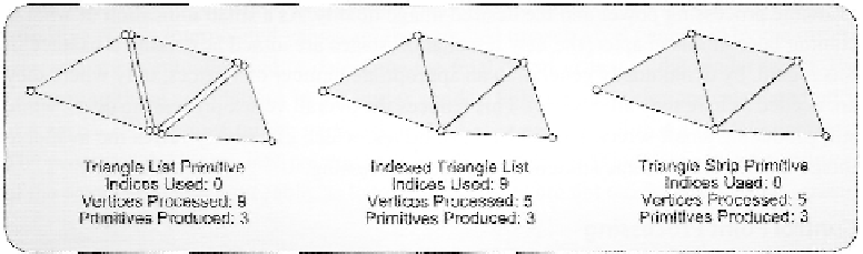
cannot share vertices. As an example, consider the geometry shown in Figure 3.17. In each
of these three cases, different primitive topologies are used to define the required model,
with varying numbers of vertices to be processed.
One additional consideration regarding vertex caching is that this operation is hard-
ware dependent. The size of the cache (and even its very existence) can vary significantly
among different CPUs. Therefore, it is a best practice to ensure that any shared vertices are
always referenced as closely together as possible in the vertex or input. In the case of the
Figure 3.17. Varying sets of geometry with different topologies, and the resulting number of required ver-
tices to be nrocessed.
Search WWH ::

Custom Search