Geology Reference
In-Depth Information
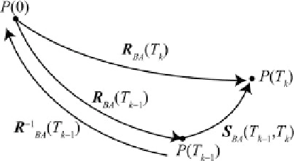
Fig. 2.27
Relationship between stage rotations and finite
reconstructions. To move a point
P
from the location at
time
T
k
1
to that at time
T
k
, it is possible to go first to the
present day through an inverse finite reconstruction, then
to time
T
k
through a direct finite transformation
Fig. 2.26
Fracture zones pattern and triple junction mi-
gration path for a system of three divergent plates. Plates
B
and
C
move about fixed Euler axes at constant rate with
respect to
A
. The relative motion between
B
and
C
cannot
be represented by a stage rotation
eters to perform the transformation of a tectonic
element from the present day location to the
position at time
T
k
relative to the conjugate plate.
Once the finite reconstruction matrices associated
with each stage boundary have been determined,
it is easy to calculate the corresponding stage ro-
tations by the following formula, whose graphical
proof is shown in Fig.
2.27
:
plates does not occur about a fixed rotation axis,
the fracture zones assume the complicate shape
showninFig.
2.26
between
B
and
C
.
Let us consider now the problem of determin-
ing stage rotations for a pair of conjugate plates
A
and
B
. In the case of oceanic basins, a subdi-
vision of the opening history in tectonic stages
is performed on the basis of the geometry of
fracture zones and an analysis of marine magnetic
anomalies. This procedure will be explained in
stage boundaries (
T
0
,
T
2
, :::,
T
n
) and the relative
position of
B
with respect to
A
(considered at
rest in the present day position) at each time
T
k
(
k
D
1,2, :::,
n
). Regarding the relative position at
time
T
0
, it can determined through a fitting algo-
rithm applied to the conjugate COBs, as we shall
see in the next section. All these relative positions
are specified through
finite reconstruction
matri-
ces
R
BA
(
T
k
), whose expression is given by (
2.18
).
The existence of these transformations is ensured
by Euler's theorem (see Sect.
2.2
). Generally,
the components of the versor
n
(
T
k
), associated
with the rotation axis at time
T
k
, are expressed
in terms of geographic coordinates (œ(
T
k
),¥(
T
k
))
of a
finite reconstruction pole P
k
. In this instance,
the triplet (œ(
T
k
),¥(
T
k
),(
T
k
)), (
T
k
)beingthe
rotation angle, specifies all the necessary param-
S
BA
.T
k1
;T
k
/
D
R
BA
.T
k
/ R
1
AB
.T
k1
/
I
k
D
1;2:::;n
(2.44)
When considering finite reconstructions, it is
always necessary to keep in mind that they do
not represent real plate motions, but the combined
result of many instantaneous or stage rotations.
Therefore, the small circle arcs associated with
a finite reconstruction pole are never expressions
of existing geological structures, contrarily to
the case of stage and instantaneous Euler poles.
This is a key point for the correct interpretation
of kinematic data, which has been discussed in
depth in a seminal paper by John Dewey (
1975
).
Now we are ready to consider the process
of construction of a
rotation model
, which rep-
resents the primary data structure that is used
in plate tectonic modelling to store the relevant
kinematic information. In fact, this file contains
the information that is needed to reconstruct both
the plate motions and the tectonic history of a
region during a selected time interval. Rotation
models are tables, generally stored in ASCII