Geology Reference
In-Depth Information
the approach used for the modelling of fracture
zones (Eq.
2.42
). The method is illustrated in
Fig.
2.25
. In this example, a point that is currently
placed along the COB of one of the two plates,
say
B
, is moved backward through time to the
locations occupied at any time
T
2
[
T
0
,
T
n
] with
respect to the conjugate reference plate
A
.
In this instance, however, the stage rotations
are performed using the full stage angles
k
and
not, as we saw in the case of fracture zones, the
halved angles. If
r
0
is the position vector of a
starting location along the continental margin of
B
, then the location at time
T
,
T
k
1
T
T
k
,isa
vector
r
(
T
) given by:
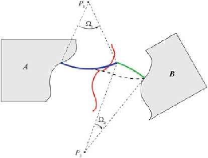
Fig. 2.25
Construction of flow lines. The sequence of
stage rotations is the same of Fig.
2.24
,andthe
dashed
line
shows the corresponding fracture zone
r.T/
D
S
BA
.T
k
;T/:::S
BA
.T
n1
;T
n2
/
S
BA
.T
n
;T
n1
/ r
0
(2.43)
A similar formula allows to calculate the lo-
cation of
r
0
at time
T
on plate
B
,
r
B
(
T
). This
algorithm can be used to test the compatibility
of existing kinematic models with real fracture
zones trend. In fact, the chain of rotations in-
cluded in Eq. (
2.42
) implies that even small errors
on the single stage rotations are enhanced after
few matrix multiplications. The algorithm, which
should reproduce the geometry of any fracture
zone, was applied for the first time by Shaw
(
1987
) in a study on the South Atlantic plate mo-
tions. More recently, Schettino and Turco (
2009
)
used this method to give further evidence that an
independent Moroccan plate existed in the central
Atlantic during the Oligocene and early Miocene.
Equation
2.42
allows to predict the geometry of
fracture zones given a plate motions model, that
is, given a sequence of stage rotations. These
lines must not be confused with the
flow lines
of relative motions, which display the path of
a representative point on a plate
B
relative to
a reference plate
A
. Figure
2.25
illustrates the
process of constructions of flow lines and the
difference with fracture zones. Although flow
lines can be traced for both oceanic basins and
zones of convergence, the latter tectonic context
historically represents the principal field of ap-
plication of this kind of kinematic representation
(Dewey et al.
1989
; Schettino and Turco
2011
).
Generally, the algorithm for generating flow lines
is simple in the case of oceanic basins and follows
This method can be used for some, but
not
for
all
, pairs of oceanic plates. Furthermore, it is
not generally applicable to the case of convergent
settings. The reason is that stage rotations exist
for some plate pairs sharing a common boundary,
but not for
any
pair of plates, not even when
they share a boundary. This theorem can be easily
proved considering the simple case of a three-
plates system. Let us consider an
RRR
triple junc-
tion like that of Fig.
2.17
. If the relative motion
of
B
with respect to
A
is described by a stage
rotation, then by definition the Euler pole
P
BA
is at
rest in the reference frame of
A
. Similarly, if the
motion of
C
with respect to
A
can be described
by a stage rotation, then the location of the stage
pole
P
CA
is also at rest in the reference frame of
A
.However,
P
BA
will not be at rest with respect to
C
, just like
P
CA
will not be at rest with respect to
B
. Therefore, the Euler vector ¨
BC
D
¨
BA
C
¨
AC
cannot be an invariant neither in the frame of
B
nor in that of
C
.Thisimpliesthatastage
pole does not exist for the plate pair (
B
,
C
), even
though both
B
and
C
move by stage rotations with
respect to
A
. For this reason, we shall use the
term “conjugate plates” only in the case of plates
sharing a common boundary (not necessarily a
spreading ridge) and whose relative motion can
be described by a sequence of stage rotations.
When the divergent relative motion between two