Geology Reference
In-Depth Information
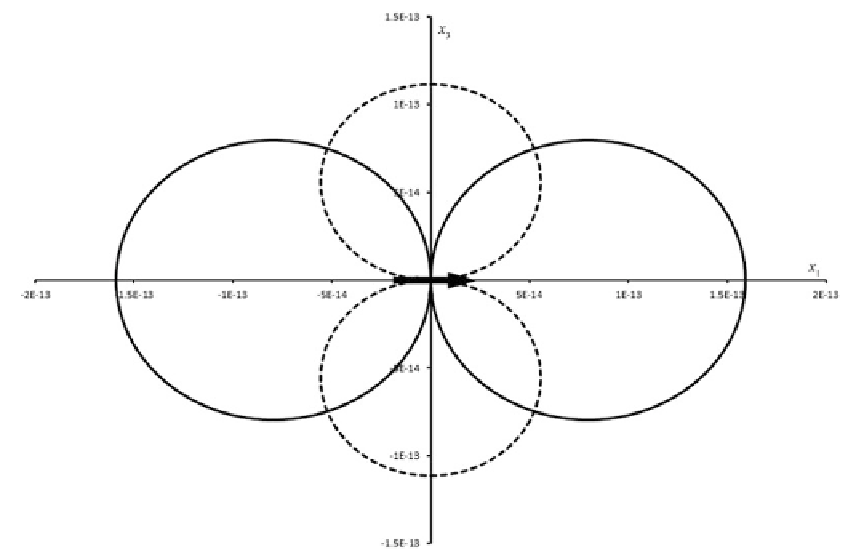
Fig. 10.8
Radial (
solid lines
) and tangential (
dashed lines
) components of displacement after the application of a unit
force at the origin in the
x
1
direction (
black arrow
). The plot has been drawn assuming
D 50 GPa and œ
D 25 GPa
components
x
i
of the position vector
r
we obtain
after some steps:
will be given by the sum of the displacements
associated with the single forces.
Let us indicate the displacement at
r
generated
by the application of a force at Ÿ by
u
(Ÿ,
r
). Using
this notation, the displacement associated with
a force couple in the
x
1
direction and with a
small arm in the
x
2
direction (Fig.
10.9
) can be
written as:
u
i
.Ÿ; r/
D
u
i
.Ÿ
1
;Ÿ
2
C
•Ÿ=2
2
;Ÿ
3
;x
1
;x
2
;x
3
/
u
i
.Ÿ
1
;Ÿ
2
•Ÿ
2
=2;Ÿ
3
;x
1
;x
2
;x
3
/
1
4 r
sin ™
u
r
D
u
1
sin ™
C
u
3
cos™
D
4 r
1
2
cos™
(10.34)
1
u
™
D
u
1
cos™
u
3
sin ™
D
Therefore, the radial component of displace-
ment is zero along the vertical axis and attains its
maximum in the horizontal plane. Conversely, the
tangential displacement (which is associated with
shear strain) is maximum along the
z
axis and
zero in the horizontal plane. Both components
have a two-lobe pattern as illustrated in Fig.
10.8
.
If a force is applied at position Ÿ instead that at the
origin, the previous formulae must be corrected
by the transformation:
x
i
!
x
i
- Ÿ
i
. In particular,
we are going to consider the case of the applica-
tion of a
force couple
in the
x
1
direction at loca-
tions (Ÿ
1
, Ÿ
2
C
1/2•Ÿ
2
, Ÿ
3
)and(Ÿ
1
, Ÿ
2
-1/2•Ÿ
2
, Ÿ
3
).
By the superposition principle, we have that in
this instance the displacement at a location
r
•Ÿ
2
C
O
•Ÿ
2
@
u
i
@Ÿ
2
D
(10.35)
Considering that
r
2
D
(
x
1
Ÿ
1
)
2
C
(
x
2
Ÿ
2
)
2
C
(
x
3
Ÿ
3
)
2
,wehave:@
r
/@Ÿ
i
D
@
r
/@
x
i
. Therefore,
@
u
i
@
u
i
@x
k
@Ÿ
k
D
(10.36)
Consequently, the total displacement can be
written as follows: