Geology Reference
In-Depth Information
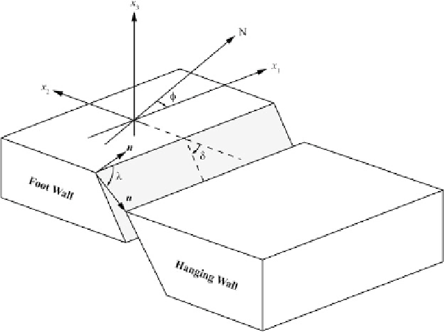
Fig. 10.7
Kinematic parameters of a source mechanism.
In earthquake studies, a fault is modeled as a planar sur-
face with normal versor
n
. The slip vector
u
describes the
relative displacement of the hanging wall block relative
to the foot wall block. It always results
u
n
a line whose orientation relative to the North is described
by the
strike
angle
¥
2 [0
ı
,360
ı
). The angle between fault
plane and the Earth's surface is the
dip
•
(0
ı
,90
ı
]. The
2
180
ı
] is between the
positive
x
1
axis and the slip vector. It is positive when
u
is
directed upwards
180
ı
,
rake
(or
slip
) angle œ
2
[
C
0. The
intersection of the fault plane with the Earth's surface is
D
This is the stick region where the “static” fric-
tional forces were overcome by the accumulated
elastic stress. Usually, this location is specified by
a single representative point in the Earth's crust
or mantle, which is called the earthquake
focus
or
hypocenter
. The coordinates (
x
0
,
y
0
,
z
0
)ofthis
point and the corresponding source time
t
0
can
be determined through specific inversion algo-
rithms (e.g., Stein and and Wysession
2003
)that
rely on the arrival times at seismic stations. The
next step is determining the
source mechanism
associated with the earthquake. This mechanism
includes the orientation of the fault along which
the rupture occurred and the slip vector of relative
motion between the two blocks or plates.
The kinematic parameters associated with a
source mechanism are the
strike
, ¥,the
dip
, •,
and the
rake
(or
slip
), œ. They are illustrated in
Fig.
10.7
. A local reference frame can be defined
aligning the
x
1
axis with the fault strike, in such a
way the fault plane dips to the right when we look
at the positive
x
1
direction. Then, the
x
2
axis is
oriented as the opposite direction with respect to
the dipping trend. Therefore, in this instance the
x
3
axis is vertical and directed upwards.
Reverse
faulting
occurs when the slip vector is directed
upwards, while downward motion is referred to
as
normal faulting
. They reflect the existence of
compressional or extensional stress fields, respec-
tively. Faults with •<45
ı
and reverse faulting
are usually termed
thrusts
. Finally, the horizontal
and vertical components of motion are indicated,
respectively, as
strike
-
slip
and
dip
-
slip
.Inpar-
ticular, in the case of pure strike-slip motion,
when an observer sees the adjacent block moving
rightwards the faulting mechanism is said to be
right
-
lateral
strike-slip, otherwise it is termed
left
-
lateral
strike-slip. Conventionally, the rake is
set to œ
D
0
ı
in the case of pure left-lateral strike-
slip motion, whereas œ
D
180
ı
in the case of pure
right-lateral strike-slip motion.
The set of parameters (¥,•,œ,
u
) is called the
focal mechanism
of an earthquake. It determines
uniquely
geometry
and
kinematics
of
the