Geology Reference
In-Depth Information
generate a measurable alternate current at the
Larmor frequency. Therefore, after a small time
interval (
1 s), in phase 2 the DC power supply is
switched off. The torque exerted by the external
field determines now a precession of the magnetic
moments about the field direction, with a Larmor
frequency that is proportional to the strength
of the total field (
2 kHz). This produces a
weak rotating magnetic field that induces a small
alternate current through the circuit. This current
decays exponentially with a time constant of a
few seconds. Therefore, it is promptly amplified
and sent to a digital counter, which furnishes a
signal frequency proportional to the geomagnetic
field intensity. The main disadvantage of proton
precession magnetometers is represented by their
sensitivity to the orientation of the external field.
For example, if the polarizing field
B
has the
same direction as
T
, then no precession will occur
and the induced current will be zero. In general,
the induced signal strength is proportional
to the sine of the angle between the Earth's
magnetic field and the axis of the solenoid. An
improvement with respect to the basic design
illustrated in Fig.
5.2
can be obtained using
toroidal cores instead of linear solenoids. The
accuracy of this kind of magnetometers can reach
0.5 nT.
Overhauser effect magnetometers are an im-
proved class of proton precession magnetome-
ters. The bottle liquid of these sensors contains a
chemical additive formed by free radicals, which
allows a different method of polarization. In this
approach, the spins of unbound electron of the
free radicals are polarized through a low-power
radiofrequency electromagnetic field. Then, the
polarization of electrons is spontaneously trans-
ferred to the protons in the liquid via a nuclear
magnetic resonance phenomenon known as Over-
hauser effect. This method allows to reduce the
required power supply by one order of magnitude
and to increase the sensitivity by two orders
of magnitude. An Overhauser magnetometer is
capable to perform readings with a 0.01-0.02 nT
standard deviation while sampling once per sec-
ond. This kind of magnetometer is widely used
in marine geophysics and is installed at several
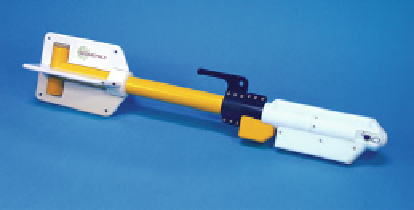
Fig. 5.3
The G-882 marine magnetometer (Picture cour-
tesy of Geometrics)
magnetic observatories. It was also used on the
Ørsted and CHAMP satellites.
The state-of-art technology in scalar magne-
tometers is undoubtedly represented by alkali
atoms (e.g., helium, caesium) vapor sensors. In
these devices, polarized laser light is transmitted
through a glass cell containing a vapor of the
alkaline substance. Again, the idea is to create
an initial alignment of spins, which then precess
about the external field axis. The sensitivity of
these devices can be as high as 0.002 nT at
1 s sample rate. Figure
5.3
shows an example
of caesium vapor magnetometer used in marine
geophysics.
The importance of oceanic magnetic surveys
for plate kinematics has been repeatedly
emphasized in the previous chapters. However,
plate tectonic modelling also relies on structural
information collected along continental margins
and continental plate boundaries. In these
areas, even small-scale land surveys can help
the identification of geological structures.
Ground-based magnetic surveys usually require
one or two proton precession or Overhauser
magnetometers. Data are acquired walking across
a rectangular grid pattern and taking readings
at more or less equally spaced grid nodes
(called
stations
). The average spacing of stations
depends from the wavelength of the anomalies
that must be mapped and ranges from less than
1-10 m. To remove the diurnal variations from
the signal, it is possible to use a second sensor,
which is called
base
-
station magnetometer
.This
is kept fixed at a nearby location, in order to
record geomagnetic field variations associated