Hardware Reference
In-Depth Information
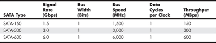
From
Table 7.9
, you can see that SATA sends data only a single bit at a time. The cable
used has only seven wires (four signal and three ground) and is a thin design, with keyed
connectors only 14mm (0.55 inches) wide on each end. This eliminates problems with
airflow compared to the wider PATA ribbon cables. Each cable has connectors only at
each end, and each cable connects the device directly to the host adapter (typically on
the motherboard). There are no master/slave settings because each cable supports only a
singledevice.Thecableendsareinterchangeable;theconnectoronthemotherboardisthe
same as on the device, and both cable ends are identical. Maximum SATA cable length
is 1 meter (39.37 inches), which is considerably longer than the 18-inch maximum for
PATA. Even with this thinner, longer, and less-expensive cable, you initially get transfer
rates of 150MBps (nearly 13% greater than PATA/133). Second-generation SATA sup-
ports 300Mbps, and third-generation SATA supports 600Mbps. Although SATA-600 uses
the same data connectors as slower versions, it use specially-designed cables to prevent
data corruption. These cables are typically marked “SATA 6Gbps.” SATA uses a special
encoding scheme called 8B/10B to encode and decode data sent along the cable. IBM ini-
tiallydeveloped(andpatented)the8B/10Btransmissioncodeintheearly1980sforusein
high-speed data communications. Many high-speed data transmission standards, includ-
ing Gigabit Ethernet, Fibre Channel, FireWire, and others, use this encoding scheme. The
main purpose of the 8B/10B encoding scheme is to guarantee that never more than four
0s (or 1s) are transmitted consecutively. This is a form of Run Length Limited (RLL) en-
coding called RLL 0,4, in which the 0 represents the minimum and the 4 represents the
maximum number of consecutive 0s or 1s in each encoded character.
The8B/10Bencodingalsoensuresthattherearenevermorethansixorfewerthanfour0s
(or 1s) in a single encoded 10-bit character. Because 1s and 0s are sent as voltage changes
on a wire, this ensures that the spacing between the voltage transitions sent by the trans-
mitter is fairly balanced, with a more regular and steady stream of pulses. This presents a
steadierloadonthecircuits,increasingreliability.Theconversionfrom8-bitdatato10-bit
encoded characters for transmission leaves several 10-bit patterns unused. Many of these
additional patterns provide flow control, delimit packets of data, perform error checking,
or perform other special functions.