Hardware Reference
In-Depth Information
9.
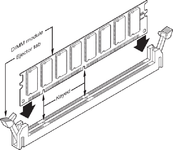
Push down on the module until the ejector tabs lock into place in the notch on the
side of the module. It's important that you not force the module into the socket. If the
moduledoesnotslipeasilyintotheslotandthensnapintoplace,itisprobablynotori-
ented or aligned correctly. Forcing the module could break it or the socket. If you're
installingRIMMs,youneedtofillanyemptyRIMMsocketswithcontinuitymodules.
Refer to
Figure 6.14
for details.
10.
Replace any cables or wires you disconnected.
11.
Close the system, reconnect the power cable, and turn on the PC.
The SIMMs used in older systems are oriented by a notch on one side of the module that
is not present on the other side, as shown in
Figure 6.15
.
The socket has a protrusion that
must fit into this notched area on one side of the module. This protrusion makes installing
a SIMM backward impossible unless you break the connector or the module.
Figure 6.16
details the notch and locking clip.
Figure 6.15
The notch on this SIMM is shown on the left side. Insert the SIMM at a 45° angle and then tilt
it forward until the locking clips snap into place.