Geoscience Reference
In-Depth Information
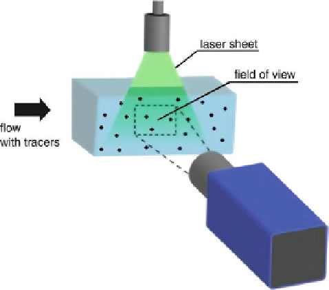
Fig. 1 Layout of a standard
PIV system
The PIV systems, developed in order to achieve these characteristics, are now used
for a wide range of fluid flow problems.
A standard PIV system now consists of a pulsed laser with optics, which creates
an illuminated sheet in the flow with tracers, one digital camera, and a computer
with a timer unit to control the system and store the data. A layout of a standard
apparatus is shown in Fig.
1
. 2D velocity fields are measured in the planar region,
illuminated by the laser light sheet and captured by the field of view of one camera.
So, in standard PIV, only the 2D components of real velocity vector in the laser
sheet can be measured, but stereoscopic PIV (SPIV) systems, able to measure also
the third component, are now available.
PIV measurements are realized in two main steps: recording and images elabor-
ating phases. A wide variety of seeding particles, illumination coding sequences,
recording techniques, and image analysis methodologies have produced many
kinds of quite different PIV methods. In fact, the most important task in using
PIV is to match all components in order to capture the desired flow features. Some
trial-error testing is inevitably required to optimize the technique for a particular
investigated situation. In the next sections, with reference to a standard 2D PIV
system, a brief description of its components and of the main typologies of image
analysis are reported.
2.1 PIV System Components and Recording Phase
A scheme of a 2D standard PIV system, with the main components, is shown in
Fig.
2
.