Geoscience Reference
In-Depth Information
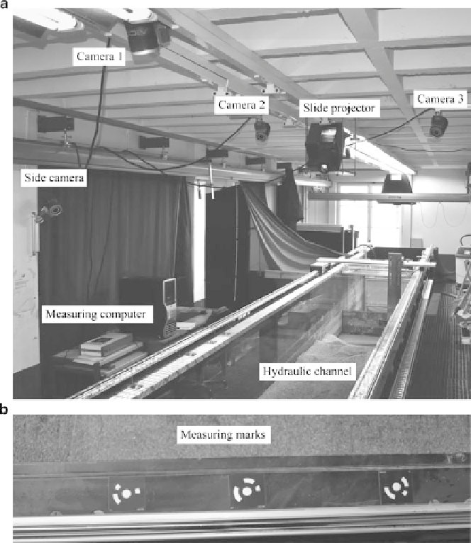
Fig. 2 The VAW test setup (a), and the measuring marks (b)
each camera. During a test, the projected grid is measured with the cameras and
3D-coordinates are calculated for each grid point.
To transform all calculated coordinates in an overall, superior coordinate sys-
tem, the hydraulic channel itself is equipped with coded measuring marks (Fig.
2b
).
The coordinates of these marks are determined prior to the test. The coded marks on
the hydraulic channel are recorded along with the projected grid and are assigned to
3D-coordinates, to allow for a 3D-Helmert-transformation of the measured grid
points into the channel system.
During a test, the channel is only lit by the slide projector. The entire breach
process, e.g., the projected grid, is recorded with the cameras. Figure
3
shows all
four camera images before reservoir filling. These images are then processed using
AICON ProSurf software. For each time step, the 3D-coordinates of the breach