Geoscience Reference
In-Depth Information
mean exit angle of the streamlines for flow entering the branch is larger at the
surface compared to the exit angles of the streamlines located at the bottom.
As it was said before, the stream tube dimensions affect the rate of the suspended
sediments delivery to the intake. The length and width of the stream tube change
along with variations of the diversion flow ratio. With the help of experimental data
as well as the three-dimensional model SSIIM2, Karami Moghadam et al. (
2010
)
studied the stream tube cases of the main channel, with inclined and vertical bank,
and drew conclusions about the stream tube width. They inferred that slopping the
main channel bank improves the flow pattern and the stream tube width in an
inclined bank case, in contrast to the vertical case, increases in the surface and
decreases in the bed much to the reduction of the sediments delivery. Also it was
found out that as the flow diversion ratio increases, the stream tube width increases
in the surface more vigorously. So, when the discharge ratio grows, more excessive
discharge is provided from the surface than from the bed, and, consequently, in
case the main channel flow contains sediments, much less of them is delivered into
the intake.
Although many researches are done on the flow pattern and the sediments in
intakes, most of them are directed toward the transmission of the bed load and to the
lateral intakes installed on rectangular channels, and none is carried out yet on
the suspended load delivery and into the intakes installed on trapezoidal ones. So, in
the present research, the case is treated with the 30
water intake installed on
trapezoidal channels. The angles of intake recommended by researchers such as
Novak et al. (
1990
) and Yang et al. (
2009
) are, respectively, 30
and 30
-45
.
2 Materials and Methods
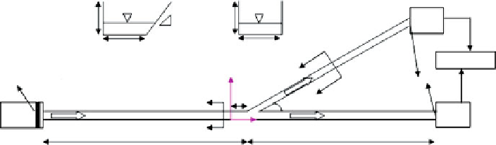
To study the flow and sediments in rivers and channels with inclined bank, some
experiments are carried out in a non-recirculating long flume with a 30
branch
channel. The experimental model was built in the hydraulic laboratory of Chamran
University, Ahwaz, Iran. Figure
3
shows the setting of the laboratory equipment.
The main channel and lateral channel were 8- and 5-m long, with bed widths of
70 cm
70 cm
Box
1
m=1.5
22 cm
22.5 cm
Section 1-1
Section 2-2
Reservoir
2
Y
Honeycomb
Slide gate
1
70 cm
2
θ
= 30
Box
flow
flow
0
X
5.5 m
1
2.3 m
Fig. 3
The experimental equipment plan of the present study