Environmental Engineering Reference
In-Depth Information
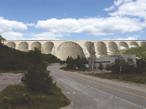
FIGURE 10.13
Daniel-Johnson Dam in Quebec. (Courtesy of Wikimedia Commons. 2012. Available at:
http://commons.wikimedia.org/wiki/Category:Daniel-Johnson_Dam.)
10.4 CONVEYANCE STRUCTURES
Conveyance structures convey water over, under, around, or through a dam. Dams are typically
designed so that water should never low over the top of the dam, because overtopping, such as
occurs during extreme loods, is a common cause of dam failures. Instead, conveyance structures
are designed to allow the release of excess water, such as the surcharge. The surcharge is that
water above the lood storage where the water level is above the emergency spillway but below the
maximum dam height (Figure 10.14). Other conveyance structures vary with the type of dam and
its intended (authorized) purpose. The conveyance structure, location, and design, as well as the
manner in which the water is released impact not only the physical, chemical, and biological char-
acteristics of the reservoir, but the downstream waters (tailwaters) as well.
10.4.1 S
pILLwayS
Spillways are intended to pass excess water from a reservoir. They include service, auxiliary, and
emergency spillways (USBR 2010). Service spillways provide continuous or frequent releases, and
may be regulated (controlled) or unregulated (uncontrolled), as illustrated in Figures 10.15 and
10.16, respectively. Auxiliary spillways are infrequently used and may be a secondary spillway,
as illustrated in Figure 10.17. Emergency spillways are intended to pass the surcharge storage and
prevent the dam from being overtopped (see Figure 10.18). Examples of uncontrolled spillways are
illustrated in Figures 10.19 and 10.20.
For gated spillways, the common gate types are tainter (radial) gates, vertical lift gates, and
drum gates (USACE 1987). Tainter gates are basically a segment of a cylinder mounted on radial
arms that rotate on anchored trunnions (Figures 10.21 and 10.22). They are simple, relatively
light, and easy to use and are one of the commonly used gate designs for navigation projects. The
vertical lift gate, with wheels (rollers) at each end, moves vertically in slots formed in the pier and
consists of a plate and horizontal girders that transmit the water load into the pier (Figures 10.23
and 10.24). Vertical lift gates are most commonly used on low-head dams (USACE 1987). Drum
gates are designed to loat on water in a chamber located in the spillway crest. A watertight sill
chamber is provided for the gate and to raise the gate, upper pool pressures are introduced into the
chamber (Figure 10.25).
Search WWH ::

Custom Search