Environmental Engineering Reference
In-Depth Information
temperature obey the same relationships of that of equations (7.4) and (7.3), but with the collector
irradiance increased by the factor (
CR
):
q
I
=
β
−
U(
T
c
−
T
a
)
η
≡
(7.7)
I
(
CR
)
T
a
+
β
(
)
I
CR
(
T
c
)
max
=
(7.8)
U
in which
CR
is to be taken from equation (7.6), and the absorbed light fraction
β
and heat transfer
coefficient
are those for the focusing system collector. It should also be noted that
I
is the solar
beam irradiance and does not include the diffuse light, which cannot be focused by the mirror. But
given the large values of the concentration ratio
CR
that are available to focusing systems, they can
operate at high efficiency even with high collector temperatures.
Focusing systems collect solar energy at a sufficiently high temperature to use that energy in
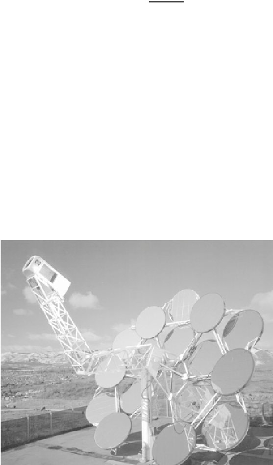
a heat engine cycle to generate electric power efficiently. Figure 7.10 shows a spherical focusing
system consisting of individual mirrors attached to a movable frame whose optical axis tracks the
sun's position in the sky. The mirrors focus on a Sterling cycle heat engine that generates 25 kW of
electrical power, with about 24% of the solar beam irradiance falling on the mirrors. An alternative
spherical system is shown in Figure 7.11 where individual mirrors arrayed about a central focusing
axis each track the sun's motion so as to focus the sun's image on a collector at the top of a central
tower. In this system, two megawatts of electrical power are generated in a Rankine cycle engine
that is heated by hot fluid circulating through the collector at the tower's top. A cylindrical collector
system can be seen in Figure 7.12, where the collector is a pipe through which fluid circulates. Nine
California power plants using cylindrical collectors generate a total of 354 MW of electrical power.
U
Figure 7.10
A parabolic mirror system focuses sunlight on a Sterling cycle heat engine that produces
electrical power. (By permission of DOE/NREL-PIX.)