Environmental Engineering Reference
In-Depth Information
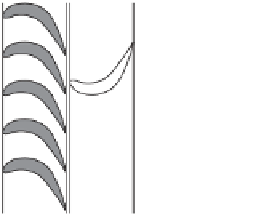
Rotor
Stator
Rotor
Stator
Rotor
Stator
Rotor
Stator
Steam
Nozzle
Steam
(a)
(b)
Figure 5.3
(a) Impulse turbine; (b) reaction turbine, schematic.
reduce the rotor speed, turbines usually employ compounding or staging. In a staged turbine, two
or more rows of moving blades (
rotors
) are separated by rows of stationary blades (
stators
), as in
Figure 5.3(a). Each pair of stator and rotor blades is called a stage. When the steam kinetic energy
is divided among
n
stages, the linear blade velocity of the rotors will be 1/2
n
that of a single rotor.
The force exerted on a rotor blade is
F
=˙
m
(v
s
−
v
b
)
newtons, where
m
is the mass flow
˙
rate of steam through the blade (kg s
−
1
),
v
s
is the tangential velocity of the steam jet (m s
−
1
), and
v
b
is the blade speed. The power generated by the blade is
P
=
F
v
b
watts. It can be shown that
s
maximum power, obtained for
v
b
=
v
s
/
2, is
P
max
=˙
m
v
/
4.
5.2.4.2 Reaction Turbine
A reaction turbine consists of rows of fixed (stator) and moving (rotor) blades. The blades are
shaped to form a converging nozzle [see Figure 5.3(b)]. Within the converging blades the steam
pressure, density and temperature decline while converting its enthalpy to kinetic energy. The steam
pressure drops steadily through all rows of blades, stationary and moving, but the steam velocity
oscillates, depending on location within the blade formation. In a reaction turbine the optimum
blade velocity is
v
b
,
opt
=
v
s
cos
θ
, where
θ
is the leaving angle of the blades, and the maximum
b
power obtained is
P
max
=˙
opt
.
In reaction turbines the pressure drops across the moving blades. This makes them less suitable
for high-pressure steam because of leakage around the blade tips and consequent loss of efficiency.
Therefore, impulse turbines are usually used for high-pressure steam, and reaction turbines are
usually used for intermediate and low-pressure steam. In addition, the high-pressure impulse stage
can reduce the steam flow to the turbine by closing off some of the first-stage nozzles; this flow
control is absent in reaction stages. In Figure 3.4 we have seen a photo of a 1500-MW steam turbine
complex for high-, intermediate-, and low-pressure stages.
In both the impulse and reaction turbines, efficiency losses are due to supersaturation, fluid
friction, leakage, and heat transfer losses. Supersaturation occurs primarily in reaction turbines
when according to thermodynamic equilibrium in the expansion process steam ought to condense,
releasing latent heat of condensation. Instead, steam remains for a while in a supercooled state
before reverting to thermodynamic equilibrium. This results in a sudden release of energy, called the
condensation shock. It is an irreversible process, causing loss in efficiency and energy availability.
m
v
,