Environmental Engineering Reference
In-Depth Information
Saturated steam
To high-pressure turbine
Steam
drum
Flue gas to stack
To low-pressure turbine
From high-pressure turbine
Boiler
Air
Feedwater
Water tubes
(risers)
Feedwater
Burner
Air
Fuel
Downcomer
Header
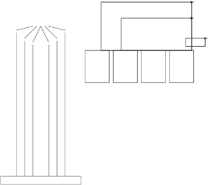
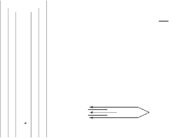
Figure 5.2
Boiler, schematic.
Figure 5.2 shows a schematic flow diagram of a common water wall boiler. Water from the
high pressure
feed water heater
at a temperature of 230-260
◦
C is further heated in the
economizer
section of the boiler to 315
◦
C, then flows into the
steam drum,
which is mounted on top of the
boiler.
5
The steam drum measures typically 30 m in length and 5 m in diameter. In the steam
drum liquid water is separated from the steam, usually by gravity. From the steam drum, liquid
water flows down the
downcomer
tubes into the
header
. From there, the hot pressurized water
flows upward (because of a negative density gradient) through the
riser
tubes, where the actual
boiling of water into steam occurs. The separated steam passes another section of the boiler,
called the
superheater,
where its temperature is raised to 565
◦
C at a pressure of 24 MPa. At this
point the temperature and pressure are higher than the critical temperature (
T
c
374
◦
C) and
=
pressure (
p
c
22 MPa) of water. The supercritical steam drives the high-pressure turbine. The
exhaust steam from the high-pressure turbine flows through the
reheater
section of the boiler, where
the temperature is raised again to about 500
◦
C at a pressure of 3.7 MPa. This steam drives the
=
5
The feed water is first heated by steam bled from the low-pressure turbine (not shown in Figure 5.2).