Hardware Reference
In-Depth Information
//Step 8
digitalWrite(motorPin4, HIGH);
digitalWrite(motorPin3, LOW);
digitalWrite(motorPin2, LOW);
digitalWrite(motorPin1, HIGH);
delay(motorSpeed);
}
5. Let's discuss the irst step in the stepper motor energizaion sequence:
// Step 1
digitalWrite(motorPin4, HIGH);
digitalWrite(motorPin3, LOW);
digitalWrite(motorPin2, LOW);
digitalWrite(motorPin1, LOW);
delay(motorSpeed);
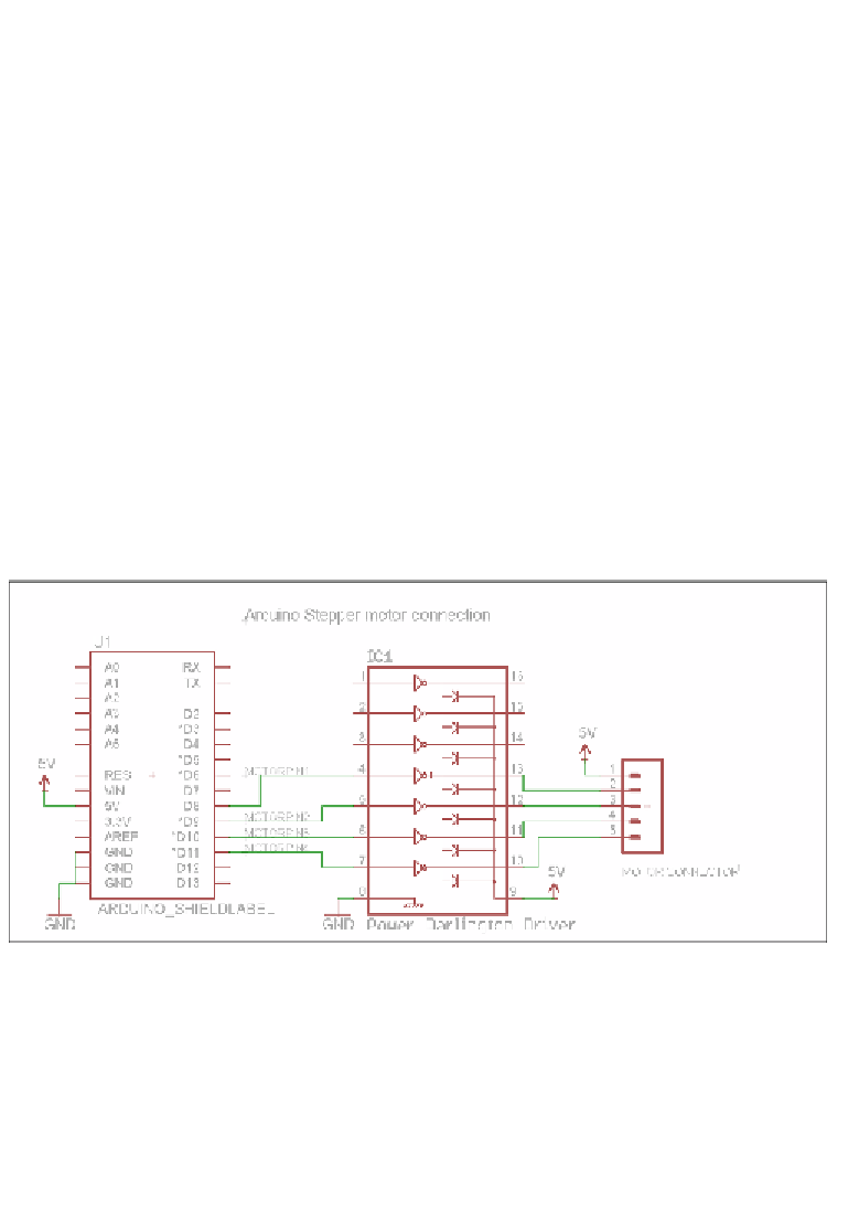
6. In the preceding lines of code, the
motorPin4
pin is set to
High
, while the other
pins are set to
Low
. As shown in the following figure, the pins
motorPin1
through
motorPin4
are connected to a power Darlington circuit. You can find a reference
to the Power Darlington circuit at
https://coefs.uncc.edu/dlsharer/
An Arduino stepper motor interface
7. When
motorpin4
(the D11 pin of the Arduino is connected to the base pin of the
power Darlington pair) is set to
high
, the transistor (which acts a switch) connects
the orange lead to the ground and energizes the coil and thereby the stepper moves
by a single step.
8. Similarly, the stepper motor's coils are energized in the sequence shown in the
table. For example, in step 2, the coils
4
and
3
are energized by seing
motorPin4
and
motorPin3
to
High
and other pins to
Low
.