Hardware Reference
In-Depth Information
Quick introduction to the I2C interface
The I2C interface was invented by Phillips Semiconductors. It is a form of serial
communicaion interface used to connect muliple slave devices (usually sensors) with a
master device (Raspberry Pi or a microcontroller) through a common interface. Each device
has a unique address that is used by the master to read or write data. There are plenty of
resources available to familiarize ourselves with the I2C interface. We will move on to the
next stage of configuring the interface.
Configuring the I2C interface on the Raspberry Pi
In the Occidentalis distribuion, the I2C drivers are installed and enabled by default. Hence,
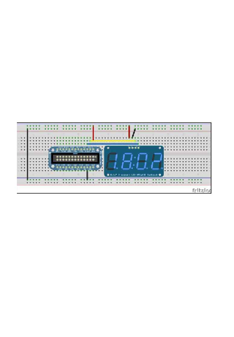
we can get started by connecing the Adafruit 7-segment backpack to the Adafruit Cobbler,
as shown in the following image. (Connecions between the Cobbler and the 7-segment
backpack are Clock pin, SCL (C)-SCL(B) Data Pin - SDA(C) -SDA(B), 3V3(C) to +(B) GND(C) to
-(B), where C is the Cobbler and B is the backpack):
7-segment backpack connections on a breadboard
Now that we have connected the Raspberry Pi, the Adafruit Cobbler, and the 7-segment
backpack, let's get started with the detecion of the backpack on the Raspberry Pi's I2C
interface and program an example.
Before we get started with the example, we need to determine the I2C bus to which the
device is connected by using the following command:
sudo i2cdetect -y 0
The command outputs a table that contains the list of devices for that paricular bus.
Since there are no devices connected to bus
0
, we scan for devices on bus
1
. In this
experiment, we are tesing the Adafruit 7-segment backpack. In the igure that follows,
the 7-segment backpack is connected to bus
1
and the device address is
0x70
. Refer
to the following screenshot: