Hardware Reference
In-Depth Information
This example is just a motivational tool and a casual reminder
for the concerned person to remain physically active.
2.
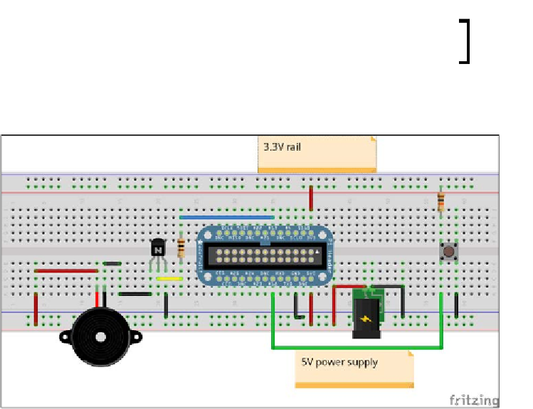
The buzzer and the switch are connected to the Raspberry Pi as shown in the
following diagram:
A button and buzzer schematic created using Fritzing
The preceding breadboard representation shows an Adafruit Pi Cobbler
mounted on a breadboard. Refer to
Project 4
,
Christmas Light Sequencer,
for a pictorial representation of how the Pi Cobbler needs to be connected
to the Raspberry Pi.
GPIO #25 of the Raspberry Pi is connected to the base of the NPN transistor,
BC547. The transistor's collector pin is connected to the negative terminal of
the buzzer. The other end of the buzzer is connected to 5 V. The emitter pin
of the transistor is connected to the ground. The transistor acts as a switch
and turns on the buzzer when the base pin is set to high.
GPIO #18 of the Raspberry Pi is pulled up to 3.3 V and a tactile switch
is connected to the GPIO switch. The other end of the switch is connected
to the ground.
3.
Let's perform a quick review of the twisted server code that runs on the Raspberry
Pi. Similar to the previous project, this example is also a simple modiicaion of the
documents/current/_down
loads/simpleserv.py
).