Environmental Engineering Reference
In-Depth Information
(a)
Electricity
Generator
Turbine
High-pressure steam
Low-pressure steam
Cool cooling water
intake from river
River
Boiler
Warm cooling
water discharge
back to river
Boiler water
Condenser
Heat source
(b)
Electricity
Fan
Generator
Evaporation
Low-
pressure
steam
Turbine
Cooling tower
Small
amount
of makeup
water
High-pressure steam
Cool
cooling
water
Boiler
Warm
cooling water
Ambient
air
Ambient
air
Boiler
water
Lake
Condenser
Heat source
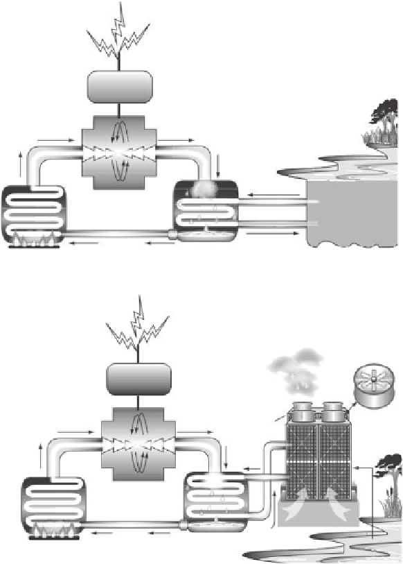
FIGURE 28.7
Cooling schemes for thermoelectric power plants. (a) Once-through cooling scheme draws water from source,
which travels through a heat exchanger and then discharges the cooling water back to the source. (b) Similarly,
wet recirculating cooling draws water from a source and cools power plant working luid. The cooling water is
then allowed to cool, generally in a tower or pond, and then recirculated through the heat exchanger.
works by pulling water from a source, using it to cool the system in a single loop while
evaporating approximately 0.5%-1.6% of water withdrawn, typically between 100 and 400 gal/
MWh. Table 28.2 summarizes these values by plant type. The rest is discharged back to
the source at approximately 3°C higher than the inlet in the United States per regulations
[17]. The large amount of water needed for withdrawal to run a once-through cooled sys-
tem puts the plant at risk during times of water scarcity and can worsen an existing water
shortage [18]. In addition, concerns over water quality and availability, negative impacts
on aquatic life, increased water return temperatures, and highly invasive zebra mussels,
which foul intake structures, are also compelling economic reasons to improve thermo-
electric plant cooling systems [5,15] through innovative technology approaches. For exam-
ple, the Garimella group at Georgia Institute of Technology (Atlanta) has investigated the