Environmental Engineering Reference
In-Depth Information
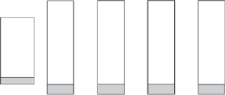
Steam ejector
(vacuum pump)
Ejector steam
Cooling water
discharge
Brine heater
Condensate
discharge
Steam in
Saline
feed
Freshwater
Brine
discharge
Brine
Brine
Brine
Brine
Condensate
back to boiler
FIGURE 27.3
Block diagram schematic showing the basic elements of an MSF distillation process. (Based on Trieb, F., ed.
Concentrating Solar Power for Water Desalination
. ed. G.A.C. [DLR] and I.O.T. Thermodynamics. Federal Ministry
for the Environment, Nature Conservation and Nuclear Energy: Stuttgart, Germany, 2007.)
27.2.3.1 MSF Distillation
The MSF process is well suited for highly saline or contaminated waters [22] because lash-
ing of water vapor from the top of brine pools allows for minimal scale formation as the
precipitates resulting from evaporation form in liquid rather than the critical surfaces of
heat transfer [12]. The irst commercial MSF plants were developed as early as the 1950s,
and the method is most popular in Middle Eastern countries, particularly in Saudi Arabia,
Kuwait, and the United Arab Emirates owing to MSF's ability to operate with the highly
saline and particulate-laden waters of the Persian Gulf [6,23]. The desalination procedure
begins by heating incoming seawater by condensing steam contained in a set of tubes run-
ning through the brine heater. The MSF process elements are depicted schematically in
Figure 27.3. To reduce energy costs, MSF plants are often combined with steam cycle power
plants, allowing for the utilization of the cooled steam from such production facilities [22]
in combined heat and power cycles. The incoming water is often pretreated with antiscal-
ants and heated to 90-110°C (194-230°F), with higher temperatures being avoided because
of concerns of scale development [24], particularly of calcium sulfate and calcium carbonate
[12]. The heated salt water is processed through a series of chambers at decreasing pressures,
causing the water to “lash” or immediately boil upon entry into the chamber [24]; that is, for
a given temperature, the chamber pressure is matched to the vapor pressure to induce boil-
ing. The number of successive chambers used can be as high as 40, although many practical
systems employ around 20 such distillate collection areas [22]. MSF plants are rated with
performance factors such as the gained output ratio (GRO), which is the mass of desalinated
water produced to mass of steam [23]. For a 20-stage MSF plant, a conventional GRO is 8 with
a typical heating requirement of about 290 kJ/kg for product water [23]. Although the highest
in terms of energy needed per unit product water produced, the MSF desalination process
provides proven reliability as well as ability to deal with highly contaminated feedwaters.
27.2.3.2 Multi-Effect Distillation
MED processes for commercial water distillation were also introduced in the 1950s [23].
This technology borrows from the plants that were irst developed to produce sugar from