Environmental Engineering Reference
In-Depth Information
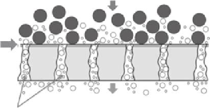
Raw water (feed)
Membrane surface
Purified water (permeate)
Membrane pores
FIGURE 20.4
Basic structure of a membrane. (From http://www.hydrogroup.biz/areas-of-use/water-treatment/membrane
-iltration.html, accessed November 22, 2012.)
Ultrafiltration
Reverse osmosis
Microfiltration
Nanofiltration
0.2 µm
0.1 µm
0.01 µm
0.001 µm
Raw water
e following
substances can
be held back:
Plankton
Algae
Turbidity
Bacteria
Suspended
substances/
solids
Macro-
molecules
Viruses
Colloids
DOC
Large
ions
Ions
Required trans-
membrane pressures:
0.2-5 bar
1-10 bar
5-10 bar
10-150 bar
FIGURE 20.5
Classiication of membranes and types of substances that can be separated by each one of them. Included are
the pressures required to drive water across each membrane type. (From http://www.hydrogroup.biz/areas-of
-use/water-treatment/membrane-iltration.html, accessed November 22, 2012.)
In most cases, it is the structure of the membrane that dictates its application. Thus, the
membranes can be classiied into membrane bioreactors, low-pressure membranes, and
high-pressure membranes:
1. Membrane bioreactors: These include MF or UF membranes immersed in aeration
tanks (vacuum system), or implemented in external pressure-driven membrane
units, as a replacement for secondary clariiers and tertiary polishing ilters.
2. Low-pressure membranes: These include MF or UF membranes, either as a pres-
sure system or an immersed system, providing a higher degree of suspended sol-
ids removal after secondary clariication.
3. High-pressure membranes: These include NF or RO pressure systems for treat-
ment and production of high-quality product water suitable for indirect potable
reuse and high-purity industrial process water.